
Membrane cleaning, part 4: Appropriate equipment and good procedures key to membrane cleaning success

Part I of this series dealt with reverse osmosis system design and configuration factors; Part II explored the problems of fouling; Part III addressed chemical methods for cleaning these systems; and Part IV delves into the appropriate equipment and good procedures.
By Stan Lueck
President, RODI Systems Corporation
Contents
A mixing tank is needed
Tank needs to be able to heat cleaning solution
Cartridge filter used to trap larger particles
Connections between cleaning system and membranes are important
A variety of factors decides the cleaning procedure
Soak in one stage while cleaning another
Experience gained through trial and error
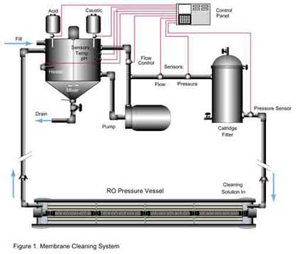
A well-equipped membrane cleaning system is illustrated below. As is evident, the system's components are commonly found pieces of equipment.
A mixing tank is needed
A mixing tank is used to prepare and hold the cleaning solution. It should be large enough to hold a sufficient quantity of that solution. A good rule of thumb is that it have a 60-gallon capacity for each 8-in. vessel (holding six elements) being cleaned. The tank should be equipped with a mechanical mixer to ensure proper dilution of the cleaning chemical before use. In the absence of a mixer, the tank should be piped so that the cleaning solution can be re-circulated through the cleaning pump and back to the tank before being returned to the vessels being cleaned. (Back to top)
Tank needs to be able to heat cleaning solution
The tank should be equipped with a means to heat the cleaning solution. In smaller systems, this can be accomplished with an electric submersible heater. In larger systems, it may require a steam coil. The temperature should be thermostatically controlled to prevent overheating the solution. A thermometer and pH sensor should be installed to monitor the temperature and pH of the solution during cleaning. The tank should be equipped with a cover to prevent splashing outside its walls and to keep foreign material from falling into it. Ideally, it should have a cone-shaped bottom or some other configuration to allow it to be drained completely. This eases considerably the cleaning of the tank before the next use.
The pump incorporated in the system has to be large enough to provide sufficient cleaning velocity (flow). It should be able to produce at least 40 gpm for each 8-in. vessel being cleaned at the same time. For instance, if the first stage of an RO system contains nine vessels and the entire stage is cleaned at once, the pump should be able to produce 360 gpm. The pressure output of the pump should be such that 50 psi of pressure drop is available across the vessel(s) being cleaned. The system should be designed to permit control of the output from the pump. A flow sensor is required to monitor the flow from the cleaning system to the vessels. (Back to top)
Cartridge filter used to trap larger particles
A cartridge filter is necessary to prevent large particles from entering the membrane treatment system during cleaning. This filter usually is located between the pump and the pressure vessels (in the supply line) rather than between the pressure vessels and the mixing tank (the return line). In this way, any foreign material such as trash in the mixing tank or inert components in the cleaning chemical will not find their way into the membrane elements being cleaned.
Because the filter is used to prevent relatively large particles from plugging the feed spacers in the elements being cleaned, cartridge hole sizes in the 10-20 micron range are generally sufficient. The pressure drop across the filter should be monitored during the cleaning process. Cartridges should be changed when the pressure drop reaches 10-15 psi.
While the size of the cleaning system will vary with the size of the membrane treatment system being cleaned, the basic components of the cleaning system will be the same regardless of system size. Materials of construction should be compatible with the cleaning solutions being used. This usually means compatibility with high or low pH. Aluminum especially should be avoided since it is soluble at high and low pH, but less so at a neutral pH. Aluminum can cause problems, even in small quantities—such as the amount that might be contained in hose connectors, for example. (Back to top)
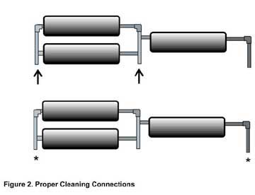
Connections between cleaning system and membranes are important
It is imperative that the cleaning system is connected correctly to the membrane system being cleaned. Never should more than one stage of vessels be cleaned at once (Figure 2). During cleaning it is important to achieve as much flow as possible. Because little water permeates through the membrane during cleaning, the majority of the flow remains in the feed spacer area of the elements, where it should accomplish more effective cleaning. If multiple stages in series are cleaned at the same time, the flow will be either low in the first stage or excessive in the second stage. Cleaning one stage at a time allows the maximum flow to be attained in each vessel. Permeate produced during the operation should be returned to the mixing tank to prevent loss of the cleaning solution.
In some cases, such as in ultrafiltration systems, vessels can be cleaned individually. In instances of extreme fouling it may be necessary to clean elements individually. This is accomplished by using a stand-alone cleaning system that incorporates a single-element vessel to hold the element being cleaned.
While vessels holding multiple elements are being cleaned, it is necessary to move the cleaning solution in the same direction as the feed water when the system is being used in the normal operating mode. The cleaning flow may be reversed only if the thrust collar is moved from the discharge end of the vessel to the feed end. If the flow is reversed without moving the thrust collar, the high differential pressure on the element stack inside the vessel can cause element telescoping since the last element in the vessel is supported only by its permeate connection (the end cap adapter). At all times, follow the membrane element manufacturer's recommendation for pressure drop across the vessel (typically 50-psi for a vessel holding six elements).
Small-to-medium sized cleaning systems usually are connected to the membrane elements by a flexible hose. Such hoses are to be in place only when cleaning is taking place. Large cleaning systems may be hard piped to the membrane system, with appropriate valves or short sections of flexible hose used to direct the cleaning solution through various stages in the system being cleaned. Regardless of the method of connection, one must be able to monitor the pressure across the vessel or stage of vessels being cleaned. The pressure drop across the vessel(s) is the primary indicator of progress during the cleaning process. It also is necessary to monitor this pressure drop to ensure that the elements are not damaged (telescoped) during the process. (Back to top)
A variety of factors decides the cleaning procedure
Actual cleaning procedures will vary depending on membrane type, cleaning system, cleaning chemical (especially if commercial formulations are used), and cleaning experience. The following procedure is a good starting point if an effective method is not already in use.
Step 1: Make sure the mixing tank is clean and that fresh cartridges have been installed in the filter. Also, make sure that the hoses or piping used to connect the cleaning equipment to the membrane system is clean.
Step 2: Thoroughly mix the cleaning solution and adjust for proper pH and temperature. Allow enough time for the pH and temperature to stabilize before starting the cleaning process. If you are using a commercial cleaning formulation, make sure to follow the manufacturer's instructions.
Step 3: Begin to transfer the cleaning solution to the vessels slowly (3 gpm for 4-in. vessels and 12 gpm for 8-in. vessels). Allow the flow to remain at this rate for approximately 15 minutes. This prevents loose particles from being dislodged suddenly and becoming caught in the feed spacers of the elements downstream.
Step 4: Increase the flow to an intermediate flow rate (6 gpm for 4-in. vessels and 24 gpm for 8-in. vessels). Allow the flow to remain at this rate for an additional 15 minutes.
Step 5: Gradually increase the flow rate until the maximum pressure drop across the vessel has been reached. As the elements in the vessel(s) become cleaner, the pressure drop will decrease. Adjust the flow frequently to keep the pressure drop at its maximum, making sure that it does not exceed the maximum allowed value. Continue to monitor the flow rate. At some point, the flow will no longer increase. This indicates that the maximum amount of cleaning has been attained. If the flow and pressure drop do not correspond to desired levels (usually those attained after a previous cleaning), it may be necessary to use a different cleaning solution. (Back to top)
Soak in one stage while cleaning another
Also, it may be advantageous to allow the cleaning solution to soak in the vessels in one stage while cleaning is started in another stage. If so, when returning to the original stage, start with the low flow step before going to the higher flow rates. Soaking loosens material that may suddenly break free and plug the feed spacer if high flows are started initially.
It is important always to flush the membrane elements thoroughly with clean water (preferably deionized water or RO permeate) before switching to a different cleaning solution. If possible, adjust the pH and temperature of the rinse water to match that of the previous cleaning solution. Mixing various types of cleaning solutions within the elements in the vessel can have disastrous results because of precipitate formation. (Back to top)
Experience gained through trial and error
Due to the variability in typical feed water sources, fouling materials and equipment characteristics, finding the most effective cleaning procedure is almost always a matter of trial and error. For this reason it is important to keep a log of cleaning activities. The log should include information such as time, date, operator ID, cleaning solution formulation, solution mixing procedures, and frequent temperature, pH, pressure and flow readings. By referring to the information gained from previous cleaning operations, the procedure will become more effective and thus more cost effective.
Read the complete series of articles:
Part 1: Before you clean RO systems, you should understand them
Part 2: Fouling problems cause reduced RO system performance
Part 3: Selecting membrane cleaning methods and materials
Part 4: Appropriate equipment and good procedures key to membrane cleaning success
About the Author: Stan Lueck is President of RODI Systems Corporation. You can contact him at 936 Highway 550, Aztec, NM 87410; Tel. 505-334-5865; Fax. 505-334-5867. (Back to top)
| Click here for more information on Companies, Careers, References, News and Products related to "membrane." |