Before you clean your RO systems, you should understand them

The use of reverse osmosis (RO) to remove a variety of unwanted contaminants from water has steadily become more common in the last few decades as the technology has been improved. One characteristic that is important for users of this process in industrial or municipal water treatment applications, however, is the RO membrane's tendency to become fouled by the contaminants it is removing from the feed water.
Colloidal solids, microbiological growth and insoluble precipitates can collect on the membrane during operation. Once a certain quantity of these deposits has built up, the treatment system has to be shut down so that the membrane can be cleaned. This results in downtime and consequently additional operating expense.
When cleaning is not performed soon enough in a use cycle, the membrane may be damaged beyond repair. In some situations the presence of fouling materials can totally preclude the use of membrane treatment as an option. Fortunately a number of pre-treatment processes are available to reduce the fouling potential of the feed water being introduced to the membrane. These methods include various types of conventional filtration, disinfection and chemical treatment. But no matter which method is used, most RO treatment systems must be cleaned regularly.
How conventional RO designs work
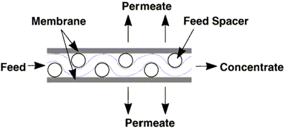
Before plant operators begin to use any cleaning procedures they should understand how reverse osmosis works. Practical RO systems use the cross-flow filtration concept, where only a portion of the water passes through the membrane. The remainder travels across the membrane and through the treatment system as waste (also called concentrate, reject or brine). This waste or concentrate flow is the mechanism that keeps fouling materials from building up too rapidly on the surface of the membrane. Cross-flow membrane treatment systems have one feed stream entering the system, and two streams, one concentrate and one permeate (the purified water) being discharged (Figure 1).
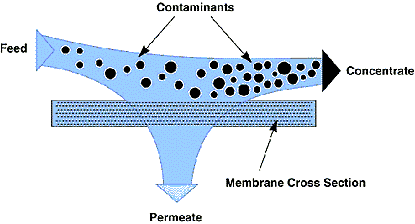
Any membrane process system is limited by the quantity of water that can be forced through a given area of membrane in a given amount of time. This flow, referred to as the membrane flux rate, is often reported in gallons per square foot per day (gfd). For a treatment system to be able to treat more water, a greater membrane surface area must be present. The membrane is operated under pressure, so it must be enclosed inside a pressure vessel (PV). For the sake of economy, the volume of these PVs must be as low as possible. The goal is to include as much membrane as possible in a small volume while still making sufficient provision for feeding water to the membrane surface and removing concentrate and permeate.
Common style uses membranes wound in spiral configuration
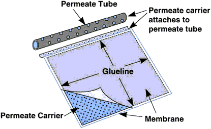
While RO membrane elements are available in a number of styles, one of the most common is the spiral wound. In the assembly of this design, two flat sheets of membrane are placed back-to-back to form an envelope (Figure 2) that contains a porous sheet of material called a permeate carrier. The envelope is glued together on three sides only. The fourth side of the envelope is attached to a perforated permeate tube. The only way the purified water or permeate can escape from the envelope is through this tube.
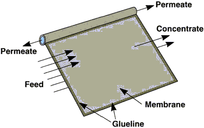
During operation the feed water, which is under pressure, flows across the membrane surface on both sides of the envelope (Figure 3). The water that passes through the membrane flows along the permeate carrier toward the open end of the envelope and leaves through the permeate tube.
In large industrial systems several envelopes are attached to a common permeate tube. These envelopes are then wrapped, or wound, around the permeate tube to form a cylindrical membrane element. Before the wrapping is carried out, however, a mesh spacer is placed between the envelopes (Figure 4).
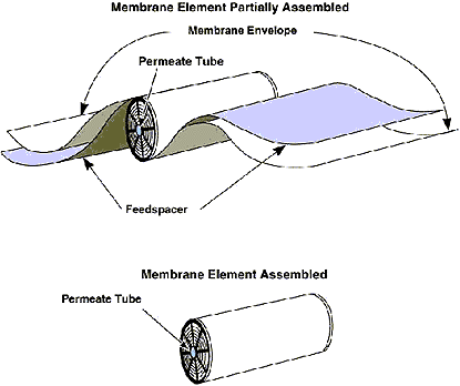
This space, called the feed channel, allows the influent stream to flow evenly distributed through the membrane element from one end to the other (Figure 5).
Editor's Note: This article is a modified version of a Technical Note that appeared in a newsletter produced by RODI Systems Corporation. Membrane cleaning procedures will be discussed in a follow-up article in the near future. For more information please contact RODI Systems at 936 Highway 550, Aztec, NM 87410; Tel. 505-334-5865; Fax. 505-334-5867.
Edited by Ian Lisk
Editor Emeritus, Water Online
