
The Economic And Operational Implications Of Utilizing A Low-Flow Bypass Pressure Reducing Valve: An In-Depth Analysis
By Assaf Heimann

Introduction
A pressure reducing valve is a vital component in water supply and in plumbing systems. Its primary function is to regulate and stabilize the downstream pressure which is supplied into a pressure-management zone. PRVs are typically employed to mitigate excessively high and often fluctuating upstream pressure from municipal water supplies or trunk mains, thereby enhancing system stability, reducing leakage rates, and minimizing rupture risks(1). However, the operational range of most PRVs is limited, with the maximum flow rate a PRV can handle being directly proportional to its size. Conversely, most PRVs can become unstable at low flow rates, were as the minimal flow that can be safely regulated being inversely proportional to the valve size(2,3,4).
The Operational Challenge Of PRVs
This operational characteristic of PRVs presents a design challenge. For a valve required to accommodate a given maximal flow, the stability of minimal flow must be compromised. In general, a larger PRV will have a higher maximum flow capacity but a higher limit to the minimum flow rate at which that PRV can stably regulate the pressure with no chattering or hunting(2,5). Since both maximal and minimal demand flow rates depend solely on the characteristics of the supplied zone, the design of the pressure-reduction system must ensure flawless operation at both the designed maximal flow, including expected maximal demand plus fire flow and safety margins, and minimal demand flow rates.
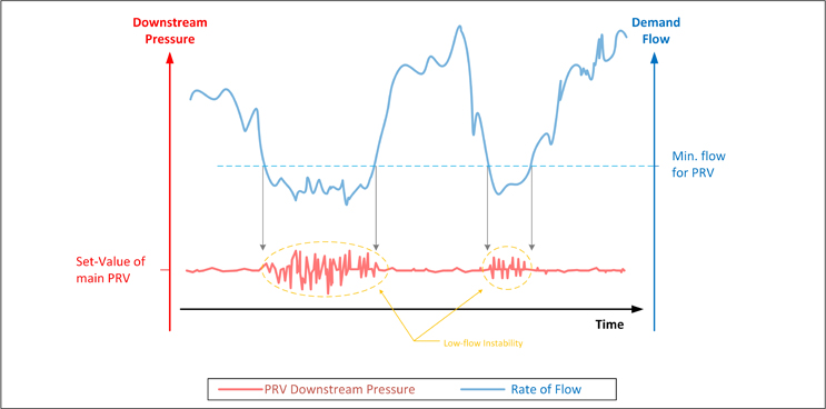
Figure 1: Low-flow instability of PRV (illustration)
The Low-Flow Bypass PRV Solution
The "set value" of a PRV is the pre-determined downstream pressure that the valve will attempt to maintain by automatically modulating to reduce the high and fluctuating upstream pressure to a lower and stable downstream pressure. This set value is typically adjusted and calibrated during the installation or commissioning of the PRV in a way that satisfies the minimal requirements in the critical point of the demand zone at maximal demand conditions (=maximal friction losses).
Operation of the combined system:
- When the flow through the system is within the capacity of the small bypass PRV, the downstream pressure is high, according to the higher setting of that PRV. Since the main PRV senses too high pressure (as it is set to a lower pressure setting) it closes and allows the low flow to run solely through the bypass PRV. i.e. the system pressure in low demand-flow conditions is higher than normal.
- As the system's flow rate increases and surpasses the bypass-PRV's capacity, the pressure-drop across the now, fully open bypass-PRV, exceeds the differential pressure between the available upstream-pressure and the main PRV’s set-pressure. In other words, downstream pressure drops below the main PRV's set point, triggering it to open gradually, augmenting flow and pressure. At this time the downstream pressure is the set-value of the main PRV, which is lower than that of the low flow bypass PRV.
- Conversely, when demand flow decreases, the bypass PRV allows the downstream pressure to climb above the main PRV's set point, causing it to close gradually, enabling the bypass PRV to regain control of flow and pressure as described in section a above.
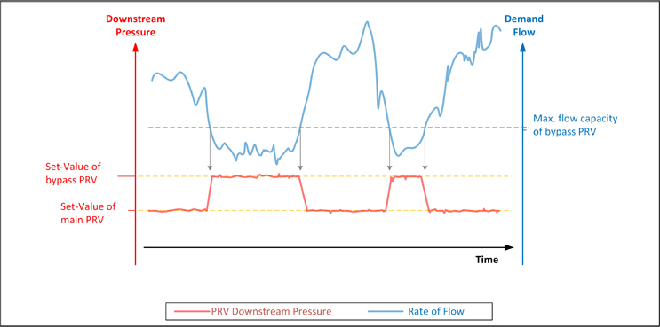
Figure 3: Zone pressure with Low-Flow Bypass PRV installed (illustration)
The Economic Implications Of Low-Flow Bypass PRV
However, the use of a low-flow bypass PRV comes with some drawbacks that may lead to operational deficiencies and additional costs:
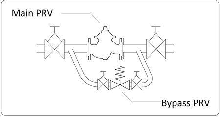
- The most obvious deficiency of adding a bypass system is, well… the addition of an auxiliary system: an additional set of devices that add complexity to the standard PRV system, increase the risk for failure (which is effectively doubled with the addition of a second regulating valve), and increase the load of maintenance work.
Direct costs include the purchase, installation, commissioning, and maintenance of the auxiliary by-pass system that includes small diam. PRV, separation valves, filter, pipes, and pipe fittings. These costs can be significant, with a minimum estimate for a 50mm/2” bypass PRV mounting to no less than 1500 USD, including installation costs(7). To that, one should add the extra maintenance costs over the years (assumed extra US$100/year). Furthermore, the risk of failure is effectively doubled with the addition of a second regulating valve.
- The use of a downstream pressure-relief valve, often used to protect the supplied system from over-pressure, introduces additional operational complexity. This relief valve, must be set at an even higher pressure than the bypass PRV, consequently dropping the overall protection level offered by the pressure reducing system.
- Indirect operational issues also arise due to the necessity to set the bypass PRV's to a higher set-pressure compared to the main PRV. For reducing the physical leakages and pipeline rupture rate in a water distribution network [WDN], it is required to maintain the lowest possible zone pressure, regardless of demand patterns. During minimal demand hours the friction losses, inflicted by the running water through the supply lines, reduces together with the reduction in the flow rate through the system. This causes the zone-pressure to increase, leading to increased physical losses(1,8,11,12) and to the degradation of system integrity. By operating a low-flow bypass PRV, the system pressure is increased further, since that bypass PRV is set higher than the main PRV! This might lead to an increase in the leakage rate and pipe-break rate whenever the demand-flow is low and the bypass PRV is active. In addition, a spring-loaded PRV is often used as a bypass valve. Spring loaded valves have a tendency for the output pressure to increase with low flows(2), which further aggravates the situation when the demand flow reduces below the transition flow.
The economic effect of that should be calculated in accordance to each specific system’s characteristics.
An example, that can provide some idea as for the magnitude of the possible costs associated with installing a low-flow bypass PRV in a WDN:
Sample system’s data:
Main PRV size ; Set-Value: 6”\150mm; 30 mwc
Bypass PRV size ; Set-Value: 2”\50mm; 37 mwc
At 30mwc *:
Physical loss rate: 5 lit/sec
Ruptures-rate: 1 pipe-break / month (=12/year)
Value of water: 1 $US/m3
Assume the low-flow conditions, for which the main PRV closes and the system pressure is regulated by the bypass PRV, exist for 2 hours a day. During that time, the system pressure increases from 30 mwc to 37 mwc.
Referencing the FAVAD theory, the Additional Water Loss rate, calculated by (1,8,11,12):
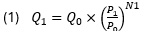
Were:
Q: Loss flow rate
P: System’s pressure
N1: Leakage index (average 1.15)
Calculating the additional leakage rate at lower demand conditions (assume N1=1.15):
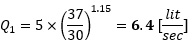
Annual cost of additional losses = (6.4-5)x3.6x2x365x1[$US/m3] = 3,680.- [$US/year]
Additional break rate, calculated by![]() (9,11,13) :
(9,11,13) :

Note: This is a rough estimation that varies dramatically for different systems.
Were:
B: Burst Frequency
P : System’s pressure
Additional leakage rate at lower demand conditions that exist for 2 hrs/day:
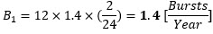
The calculation of the annual cost of additional bursts is:
Additional bursts cost [11] = (1.4-1) x 28,300[$US/burst] x 0.9[€/$] ≈ 10,190.- [$US/year] ***
Total additional costs during 20-year lifecycle of the system
(assume interest rate of 5% and lifetime of 20 years)
NPV Calculation:
(3) NPV = -I - [(OC x (1 - (1 + r)^-n)) / r]
(4) ΔNPV=-(I1-I2) - [(OC1-OC2) x (1 - (1 + r)^-n)) / r]
Were:
I: Initial Investment. In : Investment cost of option n.
OC: Operation Costs (O&M, Additional Leakage and Pipe Repair costs) OCn: Operation costs of option n.
r: Discount rate
n: Useful life
For two PRVs, one with low-flow bypass (option1) and the other without it (option 2), let’s assume the main PRV cost of option 2 is $US1,000 more than option 1, and that the maintenance costs of the main PRV (MVOC) with and without the bypass, are identical.
Bypass & installation costs (CAPEX): $US1,500
Bypass O&M costs: $US100
Additional leakage costs: $US3,680
Additional bursts related costs: $US10,190
Costs differences between the two options:
- (I1-I2) = 1,500 – 1000 = 500 - $US
- (OC1-OC2) = 100+3,680+10,190 = 13,970 - $US
Hence, the additional NPV in the example, due to the low-flow bypass installation, calculated over a period of 20 years:
ΔNPV=-500 - [13,970 x (1 - (1 + 0.05)^-20)) / 0.05] = -174,597 - $US
* In most systems, values fluctuate and are not a fixed value as in the example. For ease of calculation and to illustrate the significant impact that utilizing a low-flow bypass PRV can have, constant rates are employed.
** As the data provided here is sample data with no information such as baseline break frequency (BFnpd) described in (11), the calculation used here is the general relationship (X1.4).
*** According to (Amler A. 2020)[11], the cost of fixing a pipe break in the U.S., may be between $2,100 for a small pipe burst and as much as $54,525 for a medium pipe failure. An average value of $28,300/burst is used in the example.
Beyond the direct costs mentioned previously, reducing the rates of leakage, pipe breaks, and the formation of new leak points offers additional advantages that improve the reliability of the water supply system and impact the quality of life for customers. These benefits encompass minimizing disruptions to traffic flow, preventing interruptions to commercial activities(14), and averting damage to infrastructure. Although these advantages carry substantial economic value, quantifying their precise costs is challenging due to their indirect and multifaceted nature.
Using wide-range regulators can significantly reduce both installation and operational costs compared to the more complex low-flow bypass systems. Even in cases where the actual costs of using a bypass PRV are lower than initially estimated, the savings realized with a wide-range regulator are likely to outweigh any potential cost differences.
The Solution: PRV With Wide Regulation Range
As described, the installation of a low-flow bypass PRV is often proposed as a solution to address the instability issues that MOST (but not all!) PRVs experience when regulating high pressure differentials and low flow conditions. However, there are PRV types commercially available(3,4), that do not suffer from this specific limitation. Utilizing these wide-range regulator PRVs can enable the installation and operation costs of a pressure-reducing system to remain reasonably low compared to the substantially higher costs associated with the traditional low-flow bypass PRV solution. Even if for a specific case, these actual costs of using a bypass PRV are significantly lower than the example calculations provided, the savings from employing a wide-range regulator PRV would likely offset way over any potential cost differences between the two options. Therefore, it is highly recommended to consider the use of these wide-range regulator PRVs as a more cost-effective and efficient alternative to the traditional low-flow bypass PRV configuration.
Conclusion
In conclusion, while the use of a low-flow bypass PRV can enhance the stability of water supply systems, it is crucial to consider the associated direct and indirect costs, as well as the potential risks to system integrity. Therefore, careful design and operational planning are essential to optimize the benefits of PRVs while minimizing the associated costs and risks.
Since the potential costs associated with the use of low-flow bypass PRV may exceed any cost difference in the purchase costs of the main PRVs, it is highly recommended to prioritize the use of wide-range regulators in the design and specification of PRV systems within large water networks, avoiding the implementation of low-flow bypass PRVs whenever possible.
References:
- Farley, M.; Trow, S. Losses in Water Distribution Networks: A Practitioner's Guide to Assessment, Monitoring, and Control; IWA Publishing: London, UK, 2003.
- IRCWASH. The Performance and Selection of Pressure Reducing Valves; Engineering TR-238; IRCWASH: The Hague, The Netherlands, 1986.
- Heimann, A.; Meyer, N.; Liemberger, R. Tailoring the Specifications for Pressure Reducing Valves. In Proceedings of the 5th IWA Water Loss Reduction Specialist Conference, Cape Town, South Africa, 2009.
- Aquestia\Dorot. Series 300 Catalogue; DOROT.S300.INTRO.EN.0123C; 2023. Available online: https://www.dorot.com/Files/Files/Dorot/EngineersLibrary/Catalogs/Metal%20control%20
valves/S300/Product%20Catalog/S300-Catalog-Eng.pdf (accessed on 13 June 2024). - Zarbo, R.; Marsili, V.; Alvisi, S.; Franchini, M. Laboratory Analysis of a Piston-Actuated Pressure Reducing Valve under Low Flow Conditions. In Proceedings of The 4th International Electronic Conference on Water Sciences, 2019.
- Watts LTD. Pressure Reducing Valve with Low Flow Bypass Feature; 2008. Available online: https://media.wattswater.com/ES-M6115-74.pdf (accessed on 13 June 2024).
- Ambler, A. The Economics of Water Main Failures. Water Finance & Management, 2020. Available online: https://waterfm.com/the-economics-of-water-main-failures/ (accessed on 13 June 2024).
- International Water Association (IWA). Guidelines for Water Pressure Management; IWA: London, UK, n.d.
- Lambert, A.; Thornton, J. The Relationships between Pressure and Bursts - A ‘State-of-the-Art’ Update. Water 21 2011, 13, 24–26.
- Creaco, E.; Walski, T. Economic Analysis of Pressure Control for Leakage and Pipe Burst Reduction. J. Water Resour. Plan. Manag. 2017, 143, 12.
- Lambert, A.; Fantozzi, M.; Thornton, J. Practical Approaches to Modeling Leakage and Pressure Management in Distribution Systems – Progress since 2005. In Proceedings of the 12th International Conference on Computing and Control for the Water Industry, CCWI2013, Perugia, Italy, 2013.
- Van Zyl, J.E.; Clayton, C.R.I.; Mansell, A.D. The Effect of Pressure on Leakage in Water Distribution Systems. Proc. Inst. Civ. Eng.-Water Manag. 2007, 160, 109–114.
- Thornton, J.; Lambert, A. Managing Pressures to Reduce New Breaks. Water 21 2006, 12, 24–26.
- Sjöstrand K. Lindhe A., Söderqvist T. and Rosén L. Water Supply Delivery Failures—A Scenario-Based Approach to Assess Economic Losses and Risk Reduction Options. Water 2020, 12, 1746. https://doi.org/10.3390/w12061746
Notes:
-
Since the author lacks fluency in English, AI tools were used to improve the phrasing and proofread the text. The information presented in the article was collected and written by the author.
-
I would like to thank Eng. Mordecai Feldman, Guy Ben Shlomo and my other colleagues for their valuable inputs.
Assaf Heimann is a Hydraulic-Control Freelance Specialist with over 25 years of experience in the water industry. He excels in solving complex hydraulic control challenges, optimizing pressure management, and mitigating water hammer issues.