
Point Level vs. Continuous Level Measuring Technologies
By Lydia Miller
While point level measuring approaches are regarded as simple and user-friendly, they lack the capabilities of more sophisticated continuous measuring instruments.
Water and wastewater utilities routinely need to monitor the level of water and other liquids in various applications. These level measurements are used in many ways and situations such as:
- Level is often converted to volume, as when measuring how much of a treatment chemical is in a storage tank. For example, the height of liquid in a tank is converted to gallons.
- Level may relate more to where the liquid level is in a tank, such as when used to turn on a pump to empty a sump or lift station when liquid reaches a predetermined point.
- Level may also be used to calculate a flow measurement, as in open-channel flow applications.
There are many ways to measure either point or continuous level. Point measurement technologies include float switches, vibrating forks, capacitive sensors, and others. Continuous level technologies include radar, ultrasonic, magnetostrictive, capacitive, float-and-tape, differential pressure, and others.
With water and wastewater utilities, engineers typically tried to solve all the applications they could using point level devices. They are simple, comparatively cheap, and have been used for years, and continuous readings aren’t always necessary. Point level device outputs are simple on/off, so it keeps everything as straightforward as possible.
Many point level applications have been done with float switches. But when considering upgrades, the simplicity of switches can be maintained while using newer technologies that have no moving parts and are therefore much more reliable and require less maintenance. Vibrating fork switches are a great example of simple, single-point measurements that have been continuously improving. Some of the newest vibrating forks have the ability to do remote proof-testing and continuous health monitoring. There are switches with HART communication that can use frequency monitoring to know if the switch is in oil, water, or alcohol. They can detect settled sediment within a liquid and can even detect the presence of foam.
There are situations where having a continuous measurement can provide advantages not possible with a point device:
- Continuous measuring instruments can have functions tied to any level point using software rather than fixed device placement. Turning a pump on at a high level and off at a low level usually requires two point-level devices or a single switch with a moving float. These both require immersion in the water, and changing the switch points requires moving or adjusting the hardware. A continuous measuring instrument can provide both switching functions, and the switching points can be changed by adjusting the values in the software configuration. Features such as scum line prevention can be used to ensure the switch point is varied each time, enough to prevent scum forming on the inside of the tank. Alternate pump control modes such as common on/off or pump assist can spread the work between pumps to extend their working life.
- Alarming functions with point level require one device for each measurement point. If the control room needs to know when a lift station has hit a high alarm and when it hits a highhigh alarm, two devices are needed. A continuous measuring instrument can tell the control room where the level is and how fast it’s rising or falling. Alarms can be set at any point in the overall range as needed and changed when necessary.
- Continuous measuring instruments can usually be programmed to provide a volume measurement. Using a calculation or look-up table, the instrument can automatically convert the liquid distance measurement into a volume based on the tank configuration, even for nonlinear tank profiles such as horizontal cylinders or spheres.
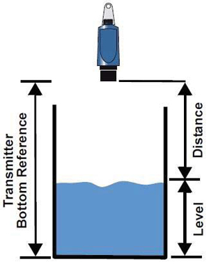
Continuous measuring instruments often stay above the liquid and are not wetted at all (Figure 1). Radar and ultrasonic instruments read from the top down, with ultrasonics being noncontact and radars having both a contacting and noncontacting version. Ultrasonic and pulse radar technologies send sound or microwave energy from a transducer toward the liquid and calculate distance by timing how long it takes for the pulse to be reflected back.
Radar can send the pulse through open space or down a metal cable or rod electrode extending into the liquid, whereas ultrasonic designs work in open space. Because top-down instruments measure the distance from the device to the surface of the liquid, they must be configured with the tank height in order to convert the measured value into the height of the liquid within the tank.
Obstructions in a tank such as brackets or ladders can cause interference with the readings from radar and ultrasonic instruments. The wrong surface can reflect the pulse and be misinterpreted as the liquid surface if the instrument is not installed properly, but today’s products are designed to minimize these problems. Unavoidable reflections can be zeroed-out in the signal processing software during the configuration process. Some ultrasonic instruments are smart enough to “learn” what a given installation sounds like. They are taught to recognize the fixed items and respond only to the moveable liquid surface. Radars are getting so advanced they can immediately discern the moving liquid surface from any tank obstructions or noise within a vessel.
Ultrasonics work on a pulse system where the sound signals are sent and then received, sent and then received. Pulse radars work similarly. A microwave pulse is sent and received before the next signal is sent. Frequency modulating continuous wave (FMCW) radar, on the other hand, doesn’t need to receive one signal back before sending the next. With FMCW radar technology, microwaves are sent in a stream of consistently varying frequencies, and the shift in the received frequency is what is used to measure the distance to the surface. Although this seems much more complicated than pulse radar, it actually allows for almost 30 times more signal to be returned to the device, resulting in much greater ability for tracking surfaces even in difficult applications with foaming, turbulence, and noise.
Are Functionality And Complexity Always Linked?
Users who avoid ultrasonic and radar technologies usually cite two concerns: cost and complexity. Both are legitimate concerns or at least were in years past. Compared to a basic float switch, an ultrasonic or radar level transmitter is more expensive and more complex, but much less so than an offering from 10 years ago or more. Newer models have come down in price and are far easier to use than their predecessors. Let’s look at a typical application case and compare the results.
Imagine a hypothetical pumping station. It has a concrete pit, 8 feet in diameter and 12 feet deep, accessible from the top via a hatch. There is a ladder to the bottom and some brackets have been installed on the walls over the years. Several lines feed into it, and there are two submersible pumps arranged in a lead-and-lag configuration. The setup requires four point level measurements. From the top down, they are:
- High-level alarm
- Lag pump on
- Lead pump on
- Pumps off
With a conventional setup, the four sensors use floats hanging from switches connected to the pump control panel. There may be a reporting function sending the pump operational status to the control room. The high-level alarm almost certainly sends a signal back to the control room, so there is at least one connection.
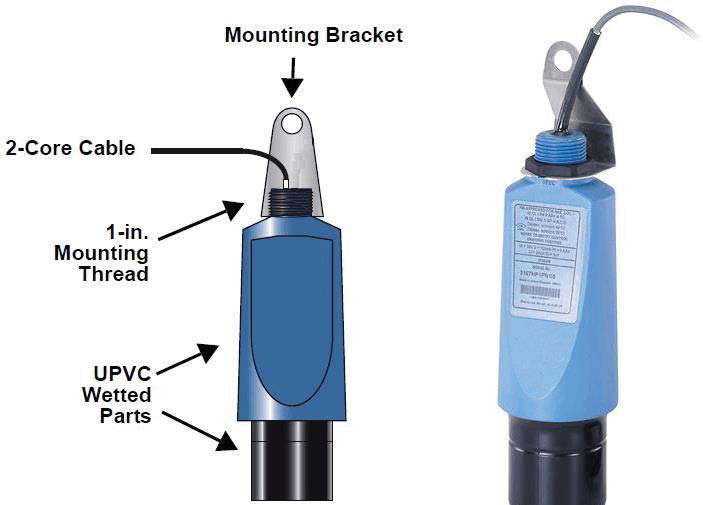
The alternative solution is to install an ultrasonic level transmitter. The capabilities discussed here reflect the Rosemount 3107 (Figure 2), but other vendors may offer comparable products. The instrument’s transmitter is designed for mounting as high as possible within the pit. It reads the distance to the liquid surface by sending out a 51 kHz sound pulse and clocking the elapsed time for the pulse to return.
Since air temperature affects the speed of sound, it has an internal temperature sensor to compensate readings as needed.
The instrument’s enclosure is made from polymers to avoid rust problems, and it can even be immersed in liquid without damage in the event of the pit flooding. It uses a 4-20 mA output with HART, so it can send all its information via simple twisted pair cabling and is loop-powered. Nothing needs to hang into the liquid, and there are no chains or cords to get tangled or coated with debris.
The transmitter alone has functions beyond taking the measurement, such as false echo mapping. It can be used directly with the pump controller to provide the information needed to turn pumps on and off, or it can be paired with a controller or readout box, which has relays to directly turn the pumps on and off or can be connected to the pump controller. Controllers in this series also provide a local display so a technician at the site can see what’s happening and have options for data logging. Pump on-and-off functions can be specified to turn the lead and lag pumps on when conditions are appropriate. Alarms can also be set as needed. In other words, all the capabilities of the conventional multiple floatswitch system can be duplicated — and more functions, features, and data are available.
Noncontacting radars are also becoming a popular choice for these types of applications, especially if foam and debris may be present. Foam can interfere with ultrasonic signals, whereas radars are not as affected by foam.
In situations where overfill may have more consequences, such as in chemical tank storage, it may be even more advantageous to use a continuous level reading along with a separate high-level alarm provided by a self-monitoring vibrating fork switch or level detector.
Advantages Of Improved Functionality
How are the ultrasonic and radar transmitter setups better from an operational point of view?
Information: Continuous level transmitters can send much more data back to the control room compared to point devices.
Using a single pair of wires, just like those connected to a single point level switch, the transmitter can send a continuous level reading and diagnostic information. Newer vibrating forks with HART can also provide additional diagnostic information.
In a situation where a problem might be developing, it is a simple matter for the control room to know what is happening at the station. Is the water level rising? Watching the data graph from continuous transmitters, it is easy to know where things are heading without having to wait for the high-level alarm to trip.
A typical example: Control room operators look at the display and see the current level. When the water reaches this point, both pumps should be running but only one is. Why? A maintenance team can check the site before it floods or even before the high-level alarm sounds. The transmitter itself can send information on its own status and warn if it is not functioning properly. A float switch can’t do that, although the enhanced vibrating forks can.
Flexibility: The HART signal from the transmitter can be used to gather primary and secondary process variables, transmit diagnostic data, and configure the transmitter. A technician can connect to the HART interface using a handheld field communicator or a laptop with a simple HART modem. Emerson and others provide PC-based software, some of it free (such as Emerson’s Instrument Inspector), to support this communication.
Using a continuous level transmitter simplifies the hardware setup when compared to multiple float switches, but it is more expensive and complex. On the other hand, once technicians learn how to configure and use these instruments, the advantages gained are well worth the effort. And naturally, setting up the second, third, and subsequent installations will be far easier.
Having additional data can simplify operations and make a utility more efficient. After the initial complexity is taken care of, the capabilities of continuous level transmitters will remain for the life of the unit, providing ongoing operational benefits.
About The Author
 Lydia Miller is a senior product engineer at Emerson Automation Solutions and has 15 years of sales engineering experience. She holds a bachelor’s degree in mechanical engineering from the University of Minnesota.