
Integration Of CFD Modeling In Wastewater Treatment Design
By Stuart Cain
This overview of computational fluid dynamic (CFD) modeling for wastewater treatment plant design reveals how it is applied to different system components, as well as why (i.e., the benefits) and when (in the design process) it should be applied.
The design of wastewater treatment plant system components is complex, as all of the individual components in the system must operate harmoniously to achieve the desired system performance. The major objectives in wastewater treatment plant design include: 1) meeting water quality standards and requirements, 2) optimizing the treatment process efficiency, 3) minimizing overall project cost, and 4) controlling ongoing operating costs and maintenance requirements. Successfully achieving these objectives is dependent upon proper design and optimization of the treatment water flow systems within the plant. These flow processes are inherently dynamic and depend heavily on flow rates, water levels, residence time, contact time, chemical concentrations, and mixing efficiencies.
Computational fluid dynamic (CFD) model studies can be reliably used to predict the complex interactions between the various treatment processes and help ensure that the design objectives are successfully met. CFD models offer the ability to study flow processes in three dimensions as well as allowing for the integration of complex filtration processes, chemical reactions, sediment transport, mixing processes, thermal processes, and aeration processes. Commercially available codes are well-suited for the types of simulations required to advance wastewater component and system designs; however, each code has individual strengths and weaknesses to be considered. Selection of an appropriate code is the first step in using modeling to support the design process. For example, CFD codes with structured meshing algorithms that are suitable for simulating transient problems involving dynamic water surfaces may not be suitable for modeling confined flows where boundary layers are important and body-fitted meshes are required. Further, mathematical models for simulating flow turbulence vary between codes, and selection of the appropriate turbulence model is important to properly simulate mixing processes, sedimentation processes, and chemical reactions. Some of the commercially available CFD codes include Fluent (Ansys, Inc.), FLOW 3D (Flow Science, Inc.), and STAR CCM+ (Siemens).
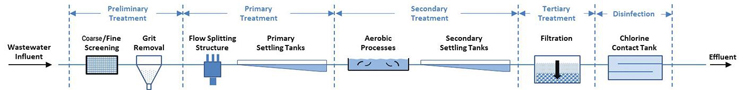
Figure 1. Conventional wastewater process flow diagram
As the capabilities of available computational resources increase, the ability of CFD models to include multiple system components becomes increasingly possible, allowing for greater accuracy in predicting the interdependencies of the system processes. Losses (due to form drag and friction), weir heights, valve positions, and energy consumed by each treatment process dictate the overall hydraulic grade line through the treatment process and affect the efficiency of each system component. Traditionally, CFD modelers look for locations in the system, between components, where model domains can be broken and boundary conditions shared between subsequent CFD models. The fewer break points required, the more accurate the prediction of the overall system performance will be.
Integration of CFD modeling into the design process usually occurs between the 30 percent and 60 percent design point. As with any modeling effort, the earlier the modeling is performed, the more useful the results are in informing the design. More and more firms are implementing simulation strategies at the 30 percent design mark.
As an illustrative example, consider the typical process flow diagram for conventional biological treatment of wastewater shown in Figure 1.
CFD simulations can be conducted to inform the designs of all treatment processes illustrated in Figure 1. The following is a brief discussion of the applicability of CFD to support the design of the illustrated system components that can benefit from flow and process optimization.
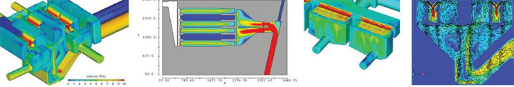
Figure 2. Screening, grit removal, and flow splitting CFD
Headworks Screening, Grit Removal, And Flow Splitting
Headworks and screening chambers can readily be modeled with CFD to simulate various configurations of fine-screen operation and resulting estimates of the flow split between the outlet channels, which feed the grit removal chambers. The grit removal chambers can be coupled with these simulations to evaluate deposition and removal efficiency of entrained grit. Flow through these components is typically controlled with overflow weirs and gates, which require the use of a CFD model with strong free-surface tracking abilities. Further, the flow must be treated as two-phase (employing a sediment scour model), as the fate of the grit in the grit chambers is of primary interest. CFD modeling of these components in the design process will optimize:
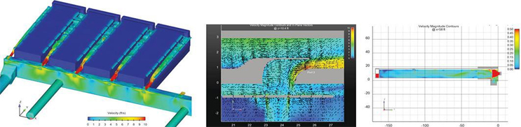
Figure 3. Settling tank CFD
- Flow and grit splits between grit chambers
- Predictions of water surface elevations at critical locations (system hydraulic grade line)
- Flow splits to the influent channels, upstream of the primary settling tanks
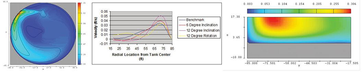
Figure 4. Contact tank CFD
Settling Tanks
Primary and secondary settling tanks rely on uniform, plug-like flow conditions to provide for settling of solids and skimming of floatables. CFD models of settling tanks typically include the influent channel, the settling chamber, and the effluent channel. A CFD model with strong free-surface capabilities is again required to accurately model this system component, as small changes in water surface elevation and weir flow can significantly impact the performance of the tank. CFD modeling of settling tanks will advance the design process by:
- Predicting the flow and solids split between operating tanks
- Predicting the water surface elevations in the influent channel, the settling tank, and the effluent channel
- Calculating the residence time of the flow within the settling tank
Contact Tanks
Flow patterns and the mixing of additives are of primary importance in optimizing the contact tank performance. CFD simulations of contact tank design alternatives can be used to accurately model the residence and contact time for the range of flow and water level scenarios during the disinfection process. Specifically, simulations integrated into the design process can be used to:
- Predict contact times
- Identify dead zones in the tank
- Optimize baffle design
- Optimize inlet and outlet arrangements
- Select optimum dosing and sampling point locations
Advances in computational resources, as well as advances in the state-of-the-art CFD code capabilities, make three-dimensional simulations an ever-increasingly useful tool in the design and optimization of wastewater treatment plant flow processes. Integration of modeling at the 30 percent design point allows engineers the full benefit of the information the models can provide and offers a reliable platform for rapidly evaluating changes as the design advances. CFD simulation results also provide defensible evidence that a final design will operate in practice as intended.
About The Author
 Stuart Cain, Ph.D., is the president of Alden Research Laboratory. He joined the company in 1996 to establish the Numeric Modeling Group and has over 25 years of experience in CFD modeling of complex water flow processes including chemically reacting flows and particulate transport. As part of his technical responsibilities at Alden, he oversees projects involving both physical and CFD modeling of hydraulic processes in water treatment, distribution, and storage systems.