
Improving Mixing In A Water Storage Reservoir Using CFD Modeling
By M. Ashraful Islam, Joseph Orlins, and Zeenat Chandrasekhar
Computational fluid dynamics (CFD) modeling was applied to a circular water storage reservoir, proving invaluable for understanding hydraulic characteristics, developing a plan for mixing efficiency, and maintaining water quality.
In the design and operation of a finished/potable water storage reservoir, an important performance criterion is the quality of water in the reservoir, which is affected by hydrodynamic mixing and water age. For example, a long residence time depresses disinfectant residuals, and uneven mixing results in zones of aged water (dead zones). Improper mixing in a water storage facility is characterized by the presence of dead flow zones and short-circuiting of flow paths from the inlet toward the outlet. Therefore, the study of flow fields in a water storage reservoir can help to identify adverse hydraulic phenomenon, and remedial measures can be taken before finalizing the design.
In recent years, CFD modeling has been used extensively to optimize the hydraulic design of water treatment, distribution, and storage systems. With the advancement of computational efficiency, state-of-the-art CFD models can resolve the complex flow fields accurately in a short time. A CFD model resolves the flow field in every computational cell of a model domain. Thus, a CFD model can be a useful tool for predicting general flow characteristics throughout a model domain, including mixing in reservoirs and for optimizing the location(s) and orientation(s) of inlets and outlets. This paper presents a case study of application of CFD modeling to improve mixing efficiency in a circular water storage reservoir.
Technical Approach
CFD models solve a form of the fundamental equations of fluid flow (conservation of mass and momentum), as well as equations representing turbulence characteristics. In general, CFD modeling of a hydraulic system consists of four steps: 1) grid generation to represent the model domain, 2) setting up the model with appropriate boundary conditions, 3) calibration and validation of the model, and 4) analyzing the model results. The study was done using STAR-CCM+, a generalpurpose CFD modeling software package. The software allows the use of both structured and unstructured computational grids and provides options for using various turbulence closure models. STAR-CCM+ uses second-order turbulence closures; therefore grid refinement and specification of correct boundary conditions are the key elements for achieving proper solutions.
Performance Evaluation
A commonly used criterion to determine the hydraulic performance in a water reservoir is the t10/T ratio, where t10 is the 10th percentile of the hydraulic residence time (T). Typically, t10/T below 0.3 indicates poor mixing1. For this study, t10 was determined from tracer tests where a conservative tracer was “injected” at the modeled inlet over a short period of time. As conservative tracers do not influence the density of water or velocity distributions, the hydrodynamics and tracer transport do not need to be coupled. The following steps were used to determine t10/T using a CFD model:
- The model was run to obtain steady-state velocity distributions for constant inflow into the reservoir and the same outflow from the reservoir. The water surface in the reservoir and temperature were assumed constant in time. The model was set to run for a sufficient number of iterations to obtain a steady-state solution.
- Once the steady-state flow field was obtained in the model, a tracer was released with the incoming inlet flow for a simulation period of 500 seconds. This tracer release method attempts to simulate the slug-dosage tracer test outlined by the American Water Works Association2. Using the velocity, mixing, and turbulence parameters computed in the previous step, the transient computations for the tracer were then advanced over a sufficient time to determine the t10/T ratio.
Computational Domain
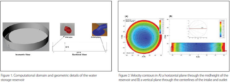
The study was conducted for a 2.1 MG potable water storage reservoir. The objective of the model study was to evaluate the hydraulic characteristics of the reservoir to optimize inlet and outlet configurations for horizontal and vertical mixing. The results of the model study were used to design a new reservoir with a capacity of 1.25 MG. Figure 1 presents the geometric configuration of the modeled reservoir with a diameter of 125 ft and a height of 24 ft. The water surface in the model was set at the top of the overflow weir, 22 ft above the reservoir bottom. Flow enters the reservoir via a 10-inch diameter inlet located 12 ft above the floor; flow exits on the opposite side of the reservoir from a 16-inch diameter outlet approximately 2 ft above the reservoir bottom.
Model Setup
The computational domain was discretized using approximately 0.5 million hexahedral cells. The size of the cells ranged from as small as 0.075 ft (around the inlet and outlet pipes) to 0.6 ft (at the water surface and tank bottom). The model simulations were conducted with a constant inflow of 1,200 gpm, and, accordingly, an inflow velocity of 5.03 ft/s was applied at the inlet. The water surface was modeled as a symmetry boundary plane and a flowsplit boundary condition was applied at the outlet. Other surfaces of the model domain were modeled as no-slip walls.
Baseline Model Run
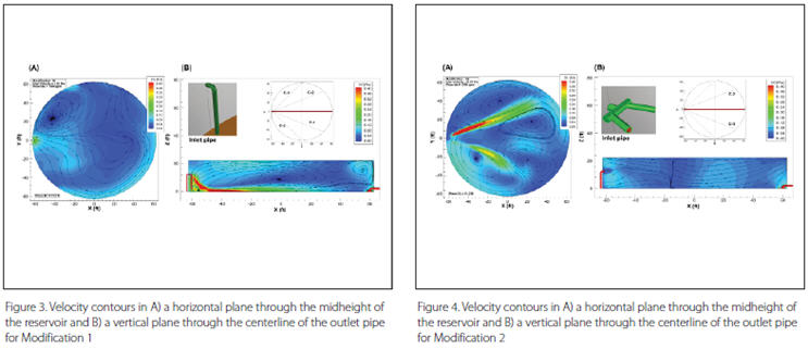
The baseline model run was conducted with the existing inlet and outlet configurations. Velocity distributions in a horizontal plane at the midheight of the reservoir (Figure 2) show the presence of a high-velocity zone along the reservoir wall. Away from the wall, velocity reduces gradually, resulting in a zone of very small velocity near the center of the reservoir. The momentum from the inlet flow creates an eddy with counter-clockwise rotation that encompasses the entire width of the reservoir. The tracer concentration at the outlet was recorded over time, with a peak at approximately 0.12 hrs. The t10/T ratio was calculated as 0.023, which indicates a significant short-circuiting in the reservoir. This can be related to the flow field shown in Figure 2 where the high-velocity plume is found to take a path along the wall to reach the outlet. The remaining portion of the flow captured in the large counterclockwise eddy eventually reaches the outlet, with the peak value decreasing continuously.
Performance Improvement
The baseline model run indicates that the existing configuration of the reservoir exhibits a significant region of dead flow that results in unsatisfactory reservoir performance. To improve mixing performance, modifications to the flow behavior in the reservoir were investigated. The flow modifications could be attained in many different ways, such as reconfiguration of the inlet and/or outlet, adding structural elements to guide the flow within the body of the reservoir, or the provision of a mechanical mixer. Two alternatives of inlet modification were investigated for this study.
The first alternative consisted of a vertical diffuser pipe with 24 2-inch holes evenly placed along the length of the inlet pipe. The diffuser ports were spaced in four columns oriented at incremental angles of 22.5°, as shown in Figure 3.
The second alternative splits the inflow pipe into two 6-inch diameter pipes. One pipe was directed toward the water surface approximately along the plane C-2; the other was directed toward the reservoir floor approximately along the plane C-3, as shown in Figure 4.
Steady-state model runs were conducted for both modifications of the reservoir. In both model runs, the mesh density, the inflow condition, and the water depth were the same as was used in the baseline model run. The model results of the first modification run are presented in Figure 3, and the results of the second modification run are presented in Figure 4.
In general, velocity contours from the modification runs show the absence of any strong velocity zones around the reservoir wall. In the horizontal planes, the first modification shows the absence of the large eddy found in the baseline run. However, as the flow originates from 24 holes for Modification 1, the initial momentum from each hole is weak, and, as a result, total flow from the diffuser pipe soon finds its way toward the reservoir floor. Streamlines in a vertical plane show the presence of eddies covering as much as the entire width. Therefore, a short-circuiting of flow along the reservoir floor can be expected for this alternative.
In Modification 2, the initial jets are much stronger in comparison to those from Modification 1. As the jets approach the water surface and the floor, each has the potential for better mixing due to longer flow paths; as a result, this option shows better performance in terms of vertical distribution of flow velocity. The dominant velocity regions are found along the midheight of the reservoir as compared to the reservoir floor or along the wall found in the other two configurations. Multiple eddies are formed in the regions away from the expanding jets. A tracer study for Modification 2 shows a peak of tracer concentration at the outlet at around 0.33 hrs. t10/T was calculated as 0.1, which is a significant improvement over the performance of the existing inlet configuration, but it still indicates less than ideal overall mixing because of the presence of dead flow zones in significant areas of the reservoir.
Conclusions
A 3-D CFD model study was conducted to determine the hydrodynamic and mixing characteristics of a circular water storage reservoir. To determine the mixing efficiency/hydraulic performance of the reservoir, the model was run with a steadystate flow, and then a tracer test was simulated by injecting a conservative tracer at the inlet.
Velocity distributions in the reservoir with existing inlet and outlet configurations show a large dead flow zone in the central part of the reservoir. The tracer model results show a t10/T ratio of 0.023, indicating poor mixing in the reservoir. To improve the mixing performance of the reservoir, two modifications of the inlet were considered. After a review of the steady-state results, one alternative was considered for the tracer run. The results of the tracer model show a significant improvement over the existing configuration in terms of the mixing characteristics, with a t10/T ratio of 0.1.
The model results showed that only changing the inlet configuration may not achieve the desired performance for water mixing. Changing the outlet configuration and/or installing structural elements (such as flow guiding baffles) in the reservoir may further improve the mixing performance.
References:
- EPA (1999). Uncovered Finished Water Reservoirs Guidance Manual.
- American Water Works Association (AWWA) (1991). Guidance manual for compliance with the filtration and disinfection requirements public water systems using surface water.
About The Authors
 Ashraful Islam, Ph.D., PE, is a principal hydraulic engineer at Alden Research Laboratory. He has 18 years of experience in numerical modeling of water flow and sediment transport processes. He specializes in the development and applications of CFD models to investigate complex hydraulics in water treatment, distribution, and storage systems. He worked as a technical lead for over 50 numerical modeling projects. Islam is a registered professional engineer in the state of Washington.
 Joe Orlins, Ph.D., PE, D.WRE, is the director of Alden’s West Coast hydraulic modeling and engineering laboratory. He has over 30 years of experience in hydraulic engineering, higher education, engineering and project management, and facilities planning and construction. He is an active member of the current Hydraulic Institute (HI) pump intake design committee tasked to prepare the next version of the HI Intake Design Standards.
 Zeenat Chandrasekhar, PE, SE, is a principal structural engineer at Kleinfelder. She has 24 years of experience as a structural engineer. She has worked on the structural design of several complex water/ wastewater structures, including steel water tanks and pump stations. Chandrasekhar is a registered structural engineer in the state of California.