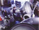
IHV & HHV Hydrovex Flow Regulators

The Hydrovex flow regulator is a vortex throttle designed to limit
flows from: storm overflows, retention basins and combined sewers.
FEATURES
- No moving parts;
- No wear;
- No auxiliary energy required;
- Large inlet and outlet;
- Corrosion free construction;
- Precise throttling;
- Small head loss during dry weather flow;
- Easy to modify throttling;
- Simple and quick to install;
- Minimum maintenance.
ADVANCED FEATURES
- Rounded head for enhanced control.
- Lighter and stronger structure.
- Positive venting to eliminate suppression during initial start-up.
- Air allowed in the vortex ensures a smooth, accurate stabilized vortex action.
OPERATING PRINCIPLES
The Hydrovex valve has a rigid housing with no moving parts. Water enters the regulator tangentially into the chamber. At low flows the flow is deflected in a smooth arc and the regulator presents practically no resistance to the flow.
As flow increases, tangential velocities in the regulator increase and eventually lead to the formation of an air-filled vortex core. The latter obstructs most of the outlet orifice without physically reducing its size. The Hydrovex now becomes an ideal throttle.
Resistance to flow compares to that of an orifice plate with a diameter as small as 1/6 that of the Hydrovex regulator outlet. The likelihood of blockage is greatly reduced.
HYDRAULICS CHARACTERISTICS
Hydrovex regulators have "S" shaped flow curves. The lower curve indicates dry weather flow, the steep curve the vortex flow.
Flow characteristics of the Hydrovex regulator are the product of the pressure on the inlet side and the following parameters:
Modification of the parameters produces an entire family of vortex regulators.
INSTALLATION
Hydrovex regulators may be installed in a separate dry chamber or a wet pit with the outflow discharging into an open channel or a fixed pipe. Dry pit installations are preferred as they provide easier access for maintenance and inspections. A clearance of 600 mm (2') should be allowed around the regulator and by-pass.
A minimum clearance below the outlet must be provided for most regulators.
Hydrovex regulators are manufactured with standard nominal inlet diameters (DN) of 100 to 1,000 mm (4" to 40").
Due to the many design parameters involved, several hundreds of possible regulator models are available. A specially-designed computer program allows John Meunier Inc. to determine optimum solutions and carry out hydraulic dimensioning.
Guarantee
Hydrovex regulators are guaranteed against manufacturing and design defects for a period of 5 years. In the event that the hydraulic characteristics fail to meet the range of accuracy of ±5% for the flows mentioned in the approval documents or if the unit is defective, John Meunier Inc. will modify or replace the regulator.
Selecting the Hydrovex regulator... Data required:
- diameter;
- threshold elevation;
- slope.
- diameter;
- threshold elevation;
- slope.
- Regulating chamber dimensions.
The Hydrovex regulator is guaranteed for an accuracy of ±5% of the design discharge.
N/A, 6290 Perinault, Montreal, H4K 1K5. Tel: 514-334-7230; Fax: 514-334-5070.
