
Getting The Most From Your Pump Station With Computational Fluid Dynamics
By Ed Wicklein

Carollo has developed computational fluid dynamics (CFD) modeling approaches and methods to evaluate and optimize pump intake hydraulics, embracing an industry trend that improves the efficiency, affordability, and reliability of water/ wastewater infrastructure projects.
For good reason, CFD modeling is being employed ever more frequently in the water sector — for smaller facilities that typically are not physically modeled due to cost relative to the project budget; for optimizing designs prior to physical modeling; and for facilities when results are needed rapidly. Using CFD modeling minimizes costs and risks while enabling verification of complex designs.
The Hydraulic Institute, a consortium of pump manufacturers, engineering designers, and end users, has agreed on generally acceptable flow conditions that the wet well geometry needs to deliver to a pump, and has provided guidance on facility layout and hydraulic conditions. Traditionally, scale physical models have been used to verify or optimize the hydraulics of larger facilities (pump systems starting at 10,000 gallons per minute [gpm] or higher, depending on system geometry). However, these models can have limitations, including the time it takes to build them, production costs, and space constraints for maintaining a model through design and construction of a project, which can take up to several years.
Many Carollo projects involve dynamic pumps, which move large volumes of water by converting input kinetic energy to liquid flow. The equipment is certified by the manufacturers to deliver a specified flow and head before it is incorporated into designs. The pump’s rated pump flow and head are based on fairly optimal flow conditions. With that in mind, it is imperative to deliver water to the pump with balanced velocity, minimal rotation, low turbulence, and minimal vortex activity for long-term reliable operation.
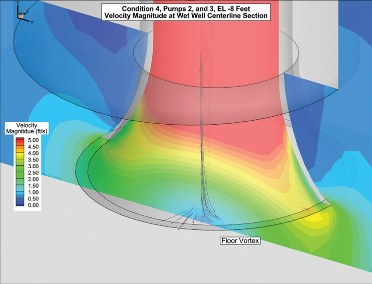
Figure 1
Case Study #1: Self-Cleaning Headworks Pump Station
The recently constructed city of San Leandro, CA, influent pump station is a 27-MGD facility that has six total submersible pumps in parallel, self-cleaning trench-style wet wells with three pumps in each. CFD modeling evaluated and optimized the system hydraulics by testing a range of flows and pump operating conditions. The model showed a uniform velocity entering the pumps, but high swirl and turbulence (almost 2 times and 1.3 times greater than recommended, respectively) and excessive vortex formation, which can be seen in Figure 1. The model was used to test geometric modifications such as fillets and a center flow splitter. Wet well modifications reduced the maximum swirl by 75%, lowered the turbulence levels, and reduced vortex formation.
Additionally, the model was used to simulate a self-cleaning cycle to evaluate the performance, as shown in Figure 2. The results showed that the upstream portion of the wet well scoured, while the hydraulic jump entrained lighter material, maintaining sufficient submergence on the downstream pump.
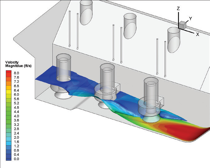
Figure 2
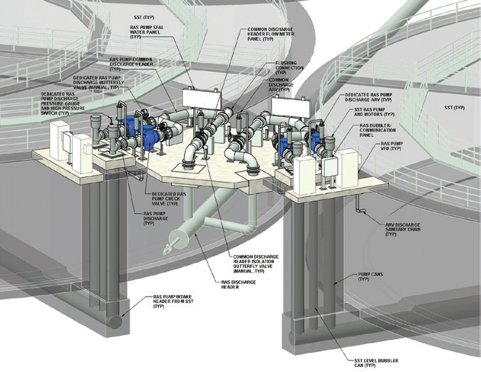
Figure 3
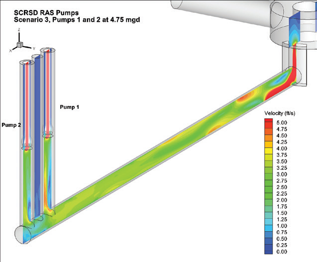
Figure 4
Case Study #2: Custom Pump Retrofit Saves Time And Money Replacing 48 Pumps
Process improvements at the Sacramento Regional County Sanitation District (SRCSD), CA, treatment plant required changes to the return activated sludge (RAS) pumping, including both higher flow and head. As highlighted in Figure 3, the RAS pumps were in open bottom cans adjacent to the secondary clarifiers. Since the piping was in place for the 24 existing clarifiers, the design goal was to reuse the existing cans, thereby saving significant construction effort.
A CFD model was used early in the design process to identify likely hydraulic conditions in the open bottom can pumping system. Overall, the CFD model showed that the intake hydraulics were acceptable with the proposed larger pumps in the existing cans. The velocity distribution on the system centerline plane is shown in Figure 4. Although flow separation was observed entering the can, the velocity was mostly uniform when it reached the pumps. Figure 5 shows a possible vortex that may develop near the pump inlet. The CFD model also found slightly elevated turbulence levels entering the pumps.
Given the overall size and complexity of the project, a scale physical model was also prepared to verify the CFD model results. The physical model verified the hydraulic conditions identified in the CFD model, such as higher, but acceptable, turbulence and intermittent vortex formation from the can wall, shown in Figure 6. Based on the results of the CFD modeling and physical modeling, the facility was upgraded with new pumps that are currently installed and in operation.
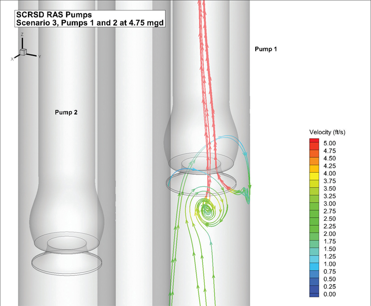
Figure 5
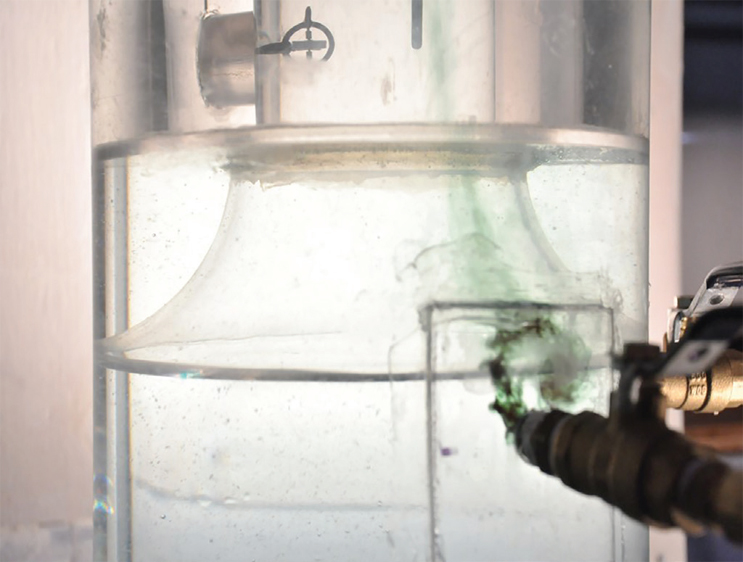
Figure 6
Summary And Conclusions
CFD modeling is frequently used to evaluate and improve the layout and geometry of new and retrofitted pump stations. Carollo has successfully used this tool for verification and/or improvement of many pump stations, enhancing our understanding of both the modeling approach as well as the analysis of results.
About The Author
 Ed Wicklein, principal technologist at Carollo Engineers, has 23 years of experience in design and analysis of hydraulic facilities using numerical models. He has conducted thousands of CFD studies of municipal facilities, including many pump intake hydraulic evaluations, as well as detailed modeling of most of the major water and wastewater treatment components and processes. He is an active member of the Hydraulic Institute Pump Intake Design Committee and the lead or co-author of four chapters of the International Water Association book CFD Modeling for Wastewater Treatment Processes.
Originally written for Currents magazine, a publication of Carollo Engineers.