
Digging The District's 21st Century Sewer System

By Carlton M. Ray
Spearheaded by three strong “ladies” and plenty of vision, DC Water’s Clean Rivers Project creates massive tunnels to rid the city of combined sewer overflows.
Over the course of the past 10 years, the District of Columbia Water and Sewer Authority (DC Water) has been planning, designing, a nd constructing the DC Clean Rivers (DCCR) Project to reduce combined sewer overflows (CSOs) to the District’s receiving waters and to mitigate chronic flooding in its historic neighborhoods. The DCCR Project consists of a series of large underground storage and conveyance tunnels, drop shafts, diversion sewers and chambers, overflow structures, and a tunnel dewatering pumping station located at DC Water’s Blue Plains Advanced Wastewater Treatment Plant. The backbone of the project is a 23-foot-diameter tunnel system that spans the length of Washington, D.C., from the southwest to northeast quadrants of the city. The tunnels, constructed in soft ground, will total over 13 miles in length and be located approximately 100 feet underground. The project is anticipated to be complete by 2022, three years before its associated consent decree deadline.

Figure 1. DC Clean Rivers Project tunnel system
Nannie is named after Nannie Helen Burroughs, who was an African- American educator and civil rights activist in the District.
Lucy was named after Howard University’s first dean of women.
DC Water’s Tunnel Boring Machines
Since the entire tunnel system is being constructed in soft ground, DC Water is employing state-of-the-art earth pressure balance tunnel boring machines, or TBMs, to build the reinforced concrete tunnel. The tunnels are being constructed in geologic stratigraphy consisting of 65-million-year-old clays and sands, referred to locally as the “Potomac Group Soils.” To date, DC Water contractors have procured three TBMs, which have been diligently digging under the nation’s capital since 2013 and are named after prominent District women (see sidebars). These machines are, in essence, underground factories that are approximately 26 feet in diameter and longer than a football field. The 80-ton cutting wheel is driven by a dozen motors. Behind the cutting wheel, the 1.3 million pound TBM shield is backed up by over 300 feet of support equipment — “the trailing gear” that provides the electrical power, hydraulics, ventilation, pumping, grout, instrumentation, and ground conditioning necessary to keep the TBM mining.
The 24,243-foot-long Blue Plains Tunnel was excavated by a TBM named Lady Bird. The 12,483-footlong Anacostia River Tunnel is currently being excavated by a TBM named Nannie. The Blue Plains and Anacostia Tunnels are primarily storage tunnels that will provide approximately 115 million gallons of the system’s 157 million gallons of total CSO storage volume. The 2,722-foot-long First Street Tunnel was recently completed by Lucy just prior to Christmas, 2015. The First Street Tunnel and the future Northeast Boundary Tunnel will increase the capacity of the existing sewer system in the District to current design standards, significantly mitigating the frequency, magnitude, and duration of sewer flooding and basement backups, and thus address chronic sewer flooding in one of the District’s largest drainage areas that have been plagued by flooding since the early 1900s.
How Do The Tunnel Boring Machines Work?
The TBMs provide an effective method of constructing tunnels in soft ground by actively supporting the ground during excavation, providing continuous ground support, and constructing behind itself a watertight final lining with a 100-year design life in a single pass. The TBMs excavate the dense sands and hard clays encountered along the tunnel alignment with a cutterhead or cutting wheel that resembles a pinwheel. The arms of the wheel are lined with ripping teeth and, depending on the ground conditions, the faces of the arms can include disc cutters. The ripping teeth, or drag bits, are effective at removing clayey and sandy soils whereas the disc cutters engage when harder materials, such as the concrete walls at shaft penetrations, cemented soils, ground improvement zones (jet grout, frozen ground), and rock, are encountered. The combination of drag teeth and disc cutters allows the TBM to handle the variety of soils and materials that are encountered along the alignment.
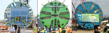
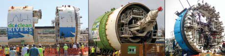
Figure 2. TOP: The 23-foot cutting wheels of Lady Bird, Lucy, and Nannie (left to right) are designed for each contract’s specific requirements and ground conditions. BOTTOM: The shield sections handle the excavated ground, provide hydraulic thrust for advancing, steer the machines, and erect the final concrete lining.
The cutterhead is also designed to support the soil during excavation, distribute and mix ground conditioning agents, and convey the excavated ground to the extraction point at the auger. Conditioning agents (foams, polymers, or bentonite) are added during excavation to turn the soil into a cohesive mass with a consistency similar to toothpaste. This consistency helps maintain and evenly distribute ground support (face pressures) during excavation and allows the auger to efficiently extract the excavated spoil in a controlled manner. The auger is the one point where excavated ground is removed from the face; the rate and direction of auger rotation controls the face pressure, which supports the unexcavated ground to control ground movements around the tunnel.
The TBM advances through the ground by pushing off the lining system with the use of hydraulic jacks. As it does so, undisturbed ground passes over the shield, which is a few inches smaller in diameter than the cutting wheel. The ground is supported by conditioning agents that are injected through the shield. At the end of the shield, about 30 to 50 feet behind the cutting wheel, precast concrete segmental rings are assembled and extruded behind the machine. The ring passes through brush seals, and annular grout is injected between the concrete rings and the ground. The wire brush seals prevent ground, grout, and water from entering the shield in the gap between the segments and shield. The annular grout, typically a two-part grout, gels quickly after injection and prevents movement of the segments and surrounding ground.
Figure 3. Tunnel boring machine cutting wheel (left) and shield components
The precast concrete segmental rings are typically 4 to 6 feet wide, and 5 to 7 segments make up a complete ring. During assembly, the ring segments are bolted together for temporary support and are connected to the previous complete ring with locking dowels. Each ring is tapered such that, depending on the rotation of a set of rings, any vertical or horizontal curve greater than about 800-foot radius can be navigated. Ethylene propylene diene monomer (EPDM) gaskets are used between the segments to prevent water ingress at the joints between segments and between rings. The combination of high-quality, high-strength, precast concrete segments and durable gaskets allows the tunnel to achieve a 100-year design life and a leakage rate less than 5 gpm per mile of completed tunnel.

Figure 4. The segment handler of Lady Bird easily manipulates the 11-footlong, 6-foot-wide, 6-ton segment prior to ring assembly.
Within the tunnel, the work environment is generally clean and dry. Water and ground ingress into the tunnel is limited and spoils removed through the auger at the face are directly conveyed into either muck cars on rails or a continuous conveyor belt that runs back to the mining shaft. Materials and precast concrete segments are delivered by locomotive along rails that are assembled behind the machine as it advances. The initial 500 to 1,000 feet of tunnel is considered part of the learning curve, and advance rates are typically reduced due to equipment assembly, troubleshooting, and downtime to install additional support equipment. After the learning curve phase, the TBM can consistently advance 50 to 100 feet a day, with scheduled downtime during the graveyard shift and on weekends to perform maintenance. Toward the end of her run, Lady Bird had a personal best 150-feet-perday production rate. At the surface, the ground movements have been imperceptible, less than 1/10th of 1 inch on average, as measured by geotechnical instrumentation placed along the alignment.
Tunnel Safety
Safety is an important consideration in any construction project. Safety in a tunnel environment has many different elements from aboveground construction: a long supply line, congested work area, multiple activities at the face, and special equipment. The job safety analysis must include an evaluation of tunnel access and egress, flood control, ventilation and air quality, illumination, and fire/explosion prevention. Site-specific incident response plans are also prepared in conjunction with local emergency responders, which include periodic tunnel rescue training.
Conclusion
DC Water’s TBMs have been instrumental in meeting project goals and the strict milestones associated with DC Water’s consent decree. Without this technology, the project would not be possible. These high-production machines have been quietly constructing a new 21st century sewer system in the District with little to no disturbance of the ground surface. Once completed, the tunnel system will reduce CSO volume to the Anacostia River in an average year of rainfall by 98 percent.
About The Author
 Carlton Ray is the director for DC Water’s Combined Sewer Overflow Long Term Control Plan called the DC Clean Rivers Project, responsible for implementing DC Water’s 25-year, $2.7 billion federally mandated consent decree to control combined sewer overflows (CSOs). Previously, he worked at the Department of Public Works in Indianapolis, IN, as chief engineer, deputy director, and CSO program lead. Ray has more than 25 years of engineering and leadership experience in both public and private civil engineering sectors, and holds a Bachelor of Science degree in Civil Engineering from Auburn University.