
Detecting defects in slurry cut-off walls used for liquid containment

Despite all precautions during construction, one cannot assume that joints remain together and that no other damage has occurred. All slurry walls incorporating geomembranes should be tested to ensure the integrity of the wall in order to protect the environment.
By Simon Emsley, PhD
Senior Geophysicist, Golder Associates
Cement-bentonite slurry cut-off walls are commonly used for the storage of very large volumes of liquids such as industrial or municipal wastewater, or for the containment of other types of waste materials. Their construction can vary in type from an excavated trench containing cementitious slurry through to an engineered barrier system incorporating geomembrane panels coupled together by a series of clutch joints.
The Construction Quality Assurance (CQA) procedure covering such walls extends to checking the slurry, the geomembrane welds, the clutch joints and the geomembrane panels placed in the trench. However, at present no checks are undertaken on slurry walls that incorporate geomembrane panels after they have been put in place. The assumption is made that the joints between panels are together and secure, and that no other damage has occurred during construction.
The case history that follows illustrates that despite full CQA measures and the construction of a slurry cut-off wall having been undertaken by an experienced contractor, the assumptions that joints remain together and that no other damage has occurred cannot necessarily be upheld.
Geomembrane inspection at mine tailings storage facility showed separated panels
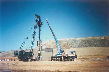
The construction of a slurry cut-off wall downstream of the tailings facility of Boliden Apirsa's Aznalcóllar mine, near Seville in Southern Spain, involved the placement of a bentonite/PFA/cement slurry in a trench. Geomembrane panels, 5.1 meters wide and up to 13 meters in depth, were placed in the slurry (see photograph) and were joined by "clutch" joints within which a swelling seal, known as hydrotite, was used.
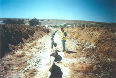
The final stage of construction involved capping the wall with a clay layer. This required the uppermost, roughly half-meter of material to be excavated (see next photograph) to remove desiccation cracks in the slurry. When excavation started, it became apparent that joints between four panels were separated or de-clutched and gaps between the panels extended down into the wall. To determine whether other joints were separated or if panels were damaged it would be necessary either to excavate the full 3-kilometer length of the wall, or use a non-intrusive geophysical survey method to test the geo-membrane.
The ability to locate defects in geomembranes used in the construction of landfills and other impoundments is well known and understood. An earlier Water Online article by Ian Bishop, PhD, who is a colleague of the author at Golder Associates (UK) Ltd., described the use of electrical techniques for detecting leaks in geomembrane liners (see Geophysical Approach Finds Leaks in Containment System Liners).
Techniques available to confirm geomembrane liner integrity
These methods offer an extremely reliable and sensitive way of ensuring the integrity of a geomembrane liner. When testing the integrity of liners of this type the test area is electrically isolated and the geomembrane acts as an electrical insulator. The task of locating separated joints and other defects in a geomembrane installed vertically in a slurry cut-off wall is problematic and complex as the standard testing techniques cannot be applied.
A new geophysical survey method had to be developed to locate the positions where joints had become separated and the presence of damage to the geomembrane panels was possible. The technique exploits the insulating, high resistive, nature of the geomembrane and is based on resistivity surveying and uses an appropriate electrode array geometry
Data acquisition accomplished with relative ease
Following initial on-site testing of the new technique, geophysical surveying of the entire 3 km wall started. Data acquisition is quick and after 2½ days data covering 540 meters of the wall had been acquired. Eight anomalies were observed in these data and the slurry wall was excavated at the location of five of them.
Defects in the geomembrane or the metal plates that had been left attached to the top of the geomembrane were seen at the location of four of the anomalies. Only one had no visible cause. It had the lowest amplitude of the five, and was considered to have resulted possibly from the hydrotite being incompletely swelled, or being more conductive than normal. This suggested that low-amplitude anomalies would not indicate the presence of defects. After this initial ground testing data acquisition over the full length of the wall continued.
Survey revealed 63 questionable locations in slurry wall
The data were processed utilising standard equations and the results covering the full length of the wall were displayed graphically. An extract from the results is shown below on the chart and shows the position of two de-clutched joints, labelled 1 and 2.
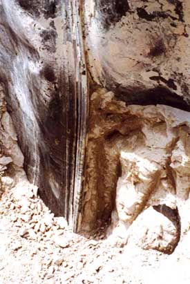
Interpretation of all the survey results indicated the presence of 63 anomalies, of which 19 were interpreted to represent the position of de-clutched joints. Excavation of the wall at the locations of these anomalies confirmed the interpretation and in one case a split seam was present in addition to the de-clutched joint. An example of one of the de-clutched joints is seen in the photograph below. One of the identified anomalies correlated with a joint that was de-clutched over a short length of the joint.
The interpretation of the results and the subsequent targeted excavation indicated that defects or other features that influenced the problematic condition were present in the wall at the location of the anomalies. The larger anomalies were related to either the presence of de-clutched joints or large holes in the membrane at the top of the wall caused by mechanical damage during capping work.
Other anomalies correlated with defects that included: small holes of the order or 0.01 to 0.02 m in diameter; splits or tears in the top of the geomembrane; and the presence of metal plates left attached to the geomembrane that were buried in the slurry wall. Where some other anomalies were indicated no defects or damage were observed. These had low amplitudes and were considered the result of incomplete swelling of the hydrotite seal and the conductive nature of the seal at the time of the survey. The greatest observed depth to the top of the de-clutched joint was 2.5 meters below ground surface.
Test method proved to be effective
In this case de-clutching of interlocking geomembrane joints for the vertical cut-off wall was observed at a number of locations. Without excavating the full length of the wall and inspecting each joint, a prohibitively costly and time-consuming operation, it would not have been possible to determine how many joints had become separated during construction. In addition, other damage to the main body of the panels could very well have been present. To address this problem Golder Associates developed a geophysical method to locate the positions where joints had become de-clutched and where other defects possible were present. The technique successfully located defects in the wall.
The method can be performed quickly, and results are available for analysis during the survey. Testing can be undertaken as construction progresses. We recommend that all slurry walls incorporating geomembranes should be tested. Such a measure should ensure the integrity of the wall and give confidence that it will fulfil its intended function, namely to protect the environment.
About the Author: Simon Emsley, PhD, is a Senior Geophysicist on the staff of Golder Associates in the firm's Maidenhead, United Kingdom office. He is responsible for technical direction of geophysical projects and the development of leading edge technology and can be reached at Tel: 44 1628 771731; Fax: 44 1628 770699; e-mail semsley@golder.com for more information on this or other geophysical methods.
Golder Associates (UK) Ltd. is the UK operating company of Golder Associates Corporation, an international group of science and engineering consulting companies. Founded in 1960, the firm has more than 2,100 employees in 80 offices worldwide and has completed project assignments in over 130 countries.