
Best Technology Available For Reliable Design Of Water Treatment Plant Hydraulics
By Stuart Cain
Treatment plant design comes in many shapes and sizes — and even dimensions. Determining the best option comes from understanding, and perhaps combining, the available options.
Designing new and modifying existing water treatment plants (WTPs) involves selecting, sizing, and integrating a sequence of hydraulic processes to achieve a target water quality. Preliminary design data often consists of the target average characteristics of the influent stream (flow rate/head and concentrations of the main constituents) as well as the target quality requirements for the effluent. The characteristics of the influent stream are either directly measured or, more often than not, estimated based on engineering judgment and experience. Sometimes the desired treatment processes are specified; sometimes the selection of the treatment alternatives is included in the design scope. Either way, treatment process performance is generally evaluated based on hydraulic modeling. Selection and implementation of the most appropriate modeling tool are critical for successful execution of the design process and for minimizing the risks associated with prototype system performance.
Modeling the hydraulic performance of any water treatment system or the performance of individual system components can be accomplished using numeric modeling, scale physical modeling, or a combination of the two techniques. Numeric modeling tools include one-, two-, and three-dimensional approaches that can predict transient as well as steady-state hydraulics, thermodynamics, and reaction chemistry. As with any numeric approach, there are approximations and assumptions, which must be chosen wisely to avoid erroneous misleading results. Further, there are certain classes of flow problems and treatment processes where the mathematical foundations of the current numeric models cannot adequately capture the required flow physics, and scaled laboratory-based physical modeling must be used to arrive at reliable solutions. Scaled physical models are not encumbered by mathematical approximations and computer resource limitations; however, scaling of all process variables simultaneously in a physical model is not possible, and scale effects must be properly accounted for in order to have confidence in resulting test data. In evaluating the performance of system components, it is not uncommon to use a combination of numeric and physical modeling approaches to predict prototype performance and advance the system design.
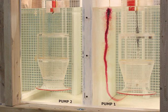
Figure 1. Scale physical modeling of pumping processes
Numeric Modeling
Numeric modeling techniques are continually evolving and the computational resources required to tackle complex flow processes are keeping pace. Simulations that were intractable five years ago are commonplace today. Complex flow phenomena as well as chemical processes and biological processes can be modeled in detail, giving the designer a powerful tool to advance the overall system design. A multitude of commercial one-, two-, and three-dimensional modeling tools are available for water treatment plant hydraulic design. Each class of tools has advantages and limitations, but can play an important role in assessing overall system performance, predicting individual treatment process performance, and informing the effects of process changes on the overall system performance.
One-Dimensional Models
One-dimensional (1D) numeric models for water treatment system and system process design generally couple a linknode model (calculating pressures at each node and velocities, flows, and head loss in each link) with empirical models simulating the treatment process component physics and chemistry at each node. Modeling of the process components is accomplished by building the theoretical performance of the treatment process into the model and imposing its effects on the overall system. Process variables are dependent on the gross flow variables and vice versa, such that the dynamics of the system as a whole can be estimated. Recently, these models have incorporated fully dynamic predictive capabilities, and the impacts of changes to individual processes or boundary conditions on the overall system performance can be simulated. Simulation execution times are on the order of hours, and multiple changes can be evaluated rapidly. With proper calibration, these models can be useful in estimating gross system performance, particularly when the system is up and operating and actual data can be fed back into the model to improve its accuracy. The current trend is to integrate this type of modeling directly into building information modeling (BIM) applications. The 1D models are limited, however, to gross system performance and are limited in their ability to predict the effects of flow distribution, particulate distribution, and localized hydrodynamics on system performance. 1D models are also limited in their ability to predict the effects of localized hydrodynamics on individual process component performance.
Two-Dimensional Models
Two-dimensional (2D) models begin to integrate the physics of the flow into the prediction of the performance of the system as well as individual system components. In general, these models allow for the simulation of lateral variations of flow within the system and system components while calculating average values for dependent variables across the depth. This becomes particularly important when trying to predict flow splits between system components as well as lateral particulate distribution within inflow boxes and discharge conduits. Water surface profiles in open channels and conduits are predictable with 2D models as long as surface roughness characteristics are known. Using 2D models, more of the hydraulics of the system components can be included in the simulation process, leading to a more accurate representation of overall system performance. With the added dimension, 2D model solution run times are generally longer than those associated with 1D models. Further, 2D models cannot capture variations of flow and other dependent variables in the vertical direction, and therefore are limited in their ability to more accurately model the hydraulic performance of many system treatment components. Modelers are beginning to couple the 1D and 2D modeling approaches to offer better system predictability than a 1D model alone can offer.
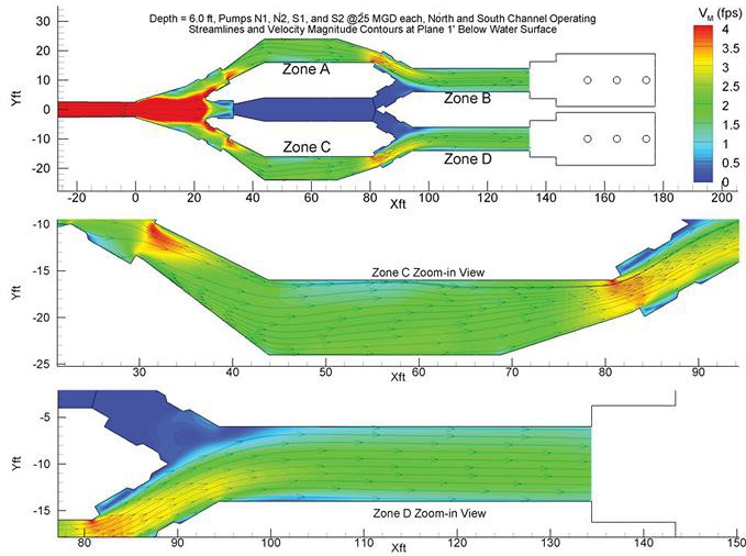
Figure 2. 2D numeric simulation of flow through a bifurcating channel
Three-Dimensional Computational Fluid Dynamics
Three-dimensional (3D) computational fluid dynamic (CFD) models are the most sophisticated and predictive numeric hydraulic models available to aid in the design process and incorporate the full three-dimensionality of the flow. CFD models can be used to predict the performance of most process flow systems and include the physics for simulating multiphase flow (gas/water, water/particulate, and aeration), chemical species transport, reaction kinetics, and mass transfer. Modeling of flow turbulence and energy dissipation is included in these models and facilitates proper prediction of complex hydraulic, chemical, and thermal mixing processes. CFD models are typically used to evaluate the performance of individual process components (settling basins, clarifiers, filters, etc.) and not used to evaluate the overall system performance. CFD models are generally very computationally intensive and, depending on the complexity of the process being modeled, can require from a few hours to a few days or weeks to complete simulations. With all of their sophistication, CFD models do have their limitations. In particular, unsteady vortical flows with the potential for air entrainment (such as those associated with pump intake hydraulics) and flow-through process systems, where the fate of floatables is of concern, pose challenges for CFD models. Further, simulation of flow events that take place over long time periods (i.e., simulation of the filling of a treatment basin over a full rainstorm hydrograph) and include rapid changes in the elevation of the water surface (flow over multiple control weirs) can be challenging to models using CFD. While sophisticated in its ability to simulate complex flows, CFD modeling requires experienced engineers to set up, run, and interpret the simulation results. Numeric models will always yield simulation results; it takes an experienced modeler to ascertain whether or not the results are physically plausible and accurate for the system under investigation.
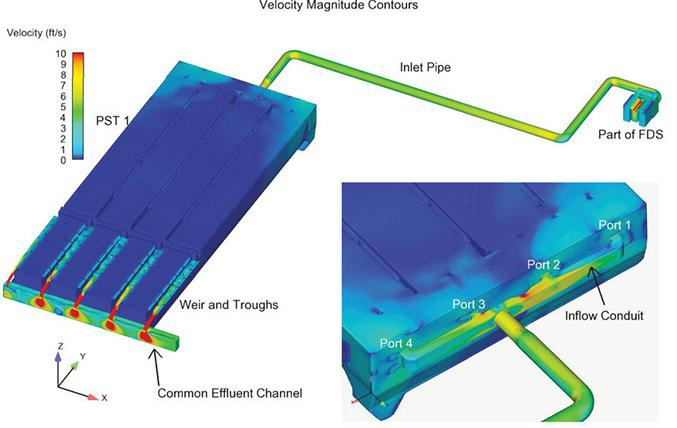
Figure 3. 3D CFD simulation of flow through a primary settling tank
Physical Scale Modeling
Laboratory-scaled physical modeling has been conducted on civil works systems for over 100 years and the scaling laws associated with implementing this modeling approach are well understood. Physical modeling is generally implemented during the design process to study critical system components that cannot be accurately simulated using CFD. One area in particular where performance cannot be accurately simulated is with pump intake structures. CFD is not capable of accurately predicting the intermittency and strength of vortical flow structures that can develop at intakes and cause degraded performance of the pumps. Physical modeling is also often employed to study complex flow splitting structures and the fate of floatables. In general, of all of the available modeling options, physical modeling offers the most accurate representation of prototype performance. As expected, however, the cost associated with conducting physical modeling activities is generally higher than computational modeling, and the time required to design, construct, and test a physical model is generally greater than for a numeric model.
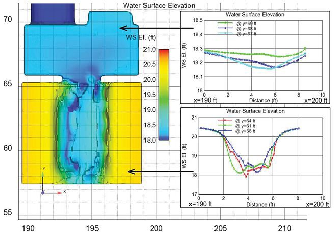
Figure 4. 3D CFD simulation of flow through a chemical reaction chamber
Hybrid Modeling
Hybrid modeling advantageously combines the aforementioned methods to offer the best approach for reliable design of water treatment system plant hydraulics. Often, physical and/or CFD modeling is used to refine the design of process components and their effect on the overall system. In some cases, the CFD model may include multiple components and their hydraulic connections if the components are hydraulically coupled and the model is not overly cumbersome. The number of process components that can be modeled in a single CFD simulation is dependent upon the computational resources required to arrive at a solution and the projected time to obtain results. Test and/or simulation data collected during the CFD/physical modeling effort is then fed into the 1D and 2D system models to more accurately predict overall system performance.
No one modeling tool can be used to comprehensively predict the overall hydrodynamic performance of a water treatment plant design. Informed selection of the correct set of hydraulic modeling tools to implement during the design process is critical in minimizing project risk and assuring that the plant operates as designed. It should be noted that many commercial tools are available to conduct 1D, 2D, and 3D CFD modeling, and several companies exist that specialize in scaled physical hydraulic modeling. The right suite of modeling tools, coupled with an experienced modeler (or modeling team), help facilitate a successful water treatment plant hydraulic design process.
About The Author
 Stuart Cain, Ph.D., is the president of Alden Research Laboratory. He joined the company in 1996 to establish the Numeric Modeling Group and has over 25 years of experience in CFD modeling of complex water flow processes, including chemically reacting flows and particulate transport. As part of his technical responsibilities at Alden, he oversees projects involving both physical and CFD modeling of hydraulic processes in water treatment, distribution, and storage systems.