Assessing Pipe Bursts And Non-Revenue Water
How much water will a pipe burst cost you? Here’s a method for determining losses.
By Vasudev Shirahatti
Water supply utilities around the developing world continue to grapple with the increasing gap in supply and demand. Inadequate delivery of clean drinking can be categorized into two basic causes – one due to source inadequacy in generating raw water, and the other a combination of demand and supply-side constraints. As metropolises grow in size, the mix of all the three is expected to compound the prevailing inadequacies of water supply systems. Take, for instance, the situation faced by the Mumbai metropolis. Mumbai Corporation of Greater Mumbai (MCGM) is one of the largest water supply systems in Asia and arguably the best-run water utility in this part of the world. The city caters to some 15 million inhabitants and the current supply-to-demand gap is in the order of 600 million liters/day (MLD), nearly 16 percent of the present supply levels. The present demand is projected to spiral to 5500 MLD by 2020. MCGM has initiated a two-pronged strategy for meeting shortfall in supply by developing other river sources for raw water abstraction along with interventions on the supply-side and demand-side managements. A basic strategy is reducing unaccounted-for water (UFW) through replacement and renewal of old pipelines. MCBM is also contemplating conversion of intermittent supply to continuous supply in combination with the installation of meters for reducing non-revenue water.
Unlike the city of Chicago, which has Lake Michigan as its next-door neighbor, many other metropolises have to depend on raw water transmitted over large distances. Raw water for the city of Mumbai is sourced from rivers 60 miles away through large-diameter transmission mains. The preferred option for water conveyance is by gravity pipeline. In many locations, due to topography, gravity conveyance is not a feasible option, in which case large-scale pumping have to be relied upon. From the treatment plant outlet, clear water is pumped to a hill reservoir and supplied by gravity to service reservoirs that are located within the city for fulfilling water demands over a 24- hour cycle. A common problem of surface transmission is that of expansion-joint leakage and unauthorized tappings off the pressure main. Although many utilities decline to put out statistics on unaccounted-for water, studies have shown that in metropolises like Delhi and Mumbai, UFW in the transmission and distribution systems accounts for nearly 40 percent of gross supply. As utilities grapple with higher costs of throughput production by resorting to a cross-subsidy-based tariff regime, any unaudited shortfall in supply can affect their balance-sheet top-line in a significant way. It is in this context one has to appreciate the debilitating impact of a major pipe burst. A pipe burst on a city water line often results in the loss of hundreds of thousands of gallons of precious water; additionally, the repairing time of the damaged portion means delay in resuming supply. A typical news report (Times of India in September 2014) ran thus: “…century old cast-iron Tansa pipeline in Mumbai burst with a 3 feet crack in pipeline during supply hours around 5 AM. Despite closing the valve water gushed out for a while due to hydraulic pressure. No spot repairs were possible and a section of the pipeline had to be replaced causing much delay in resuming supply…” Similarly, in another reported incident, a JCB (excavator) impacted a buried pipeline in Navi Mumbai during road excavation works, puncturing the steel pipeline and resulting in the loss of much-valued treated water. It is common in India to provide pre-stressed concrete pipes for urban water transmission. If the joints between two pipes become weak due to wear and tear, heavy traffic on roads sometimes trigger huge leaks through joints, causing loss of water.
While the reasons for a burst in a steel pipeline could be multifarious, and while immediate remedial steps should then be initiated, perhaps what is more critical is the prevention of excessive loss of water. Towards this end, it is necessary to understand the mechanics of rupture flow. To be true, pipe rupture condition is not considered a design basis in the design of pipeline. However, pipe burst flow analysis will enable hydraulic engineers to plan necessary pipeline protection measures at the design stage itself. Rupture simulation on the finalized pipeline profile can generate velocity variations in the burst pipe. Elaborate software is not necessary. This writer has developed a finite difference computational procedure for solving the mass oscillation equation amenable on Excel worksheets. The results of this analysis will generate useful information for air-vent sizing, selection of closing time of the control valve, and also in making alterations to the pipeline profile. Understanding of hydraulics of rupture flow thus provides a handle on minimizing loss of water should a burst occur on the pipeline.
Pipe rupture flow can be modeled through an understanding of development of unsteady flow in a pressure pipeline. The steady state hydraulic gradeline (HGL) over the pipeline is simply that joining the free surface of upstream balancing reservoir with that in the terminal service reservoir. In the steady state slope of this HGL is indicative of the discharge in pipeline. When a burst occurs, the initial steady state HGL instantly drops down to meet the atmospheric conditions at the burst location. The instantaneous grade line is expected to be curved and as flow acceleration takes place (owing to steepness of the hydraulic gradient), pipe resistance is mobilized, causing the grade line tends to attain more and more linear shape. Pipe resistance loss, which at the instant prior to burst is the steady state head loss corresponding to the controlled flow, starts to build up as the unsteady flow velocity increases. The differential head between the upstream reservoir and the burst location gets gradually curtailed due to ever-increasing pipeline resistance and, as time elapses, attains equilibrium with the head loss. At this instant the pipe burst flow registers its peak. Unless the control valve provided near the head water tank closes automatically or is closed manually, the tank may discharge all its contents. Normally, the control valve provided on the pipeline is set to trip automatically as soon as it senses increased velocity in the pipe and a trigger for initiating automatic closure can be set. As the control valve is triggered to close, the local head loss due to the closing valve augments the total head loss in the line. Once the total head loss out-strips the gross head between the hill tank and burst location, a continuous water column cannot be sustained any longer and the water column is broken at the valve location. The unsteady flow after flow separation is due to lesser differential head corresponding to elevation of valve location and burst location. This head diminishes instant-to-instant, owing to the moving away of the free draining column downstream of the closing valve. The rate of diminishing is dependent on the profile. If the profile is horizontal the head is conserved, while in a concave profile the head diminished. Pipeline space behind the closed valve is vacated and severe vacuum conditions develop; unless this space is vented through air vents, the pipe could suffer buckling damage.
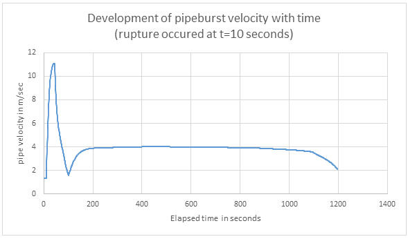
Typical pipe burst flow velocities are computed for an assumed water supply pipeline delivering 5 cubic meters/second (m3/sec) of steady flow to a service reservoir located 5,000 meters (m) away. The following system parameters are assumed for this exercise: elevation of upstream balancing reservoir of 400 m; conveyance main diameter of 2.204 m; internal cement mortar lining and butterfly valve provided 100 m away from the source at a lower elevation of 50 m and set to close automatically. It is also assumed that the trip-set velocity is 120 percent of the steady state velocity, time of control valve closure is 90 seconds, and head loss characteristics resemble exponential curve. The location of burst is assumed at distance 200 m ahead of the service reservoir at an elevation of 7 m.
Velocity variations in the burst pipe generated through the simple computational procedure are presented in the attached figure. The analysis generated the following inputs:
- Closure of the control valve starts within a second of the instant of pipe burst assumed to occur at t=10 seconds. Burst pipe velocity breaches the assumed trip-set velocity of 1.62 m/sec, which is 120 percent of the steady state velocity of 1.35 m/sec. The initial differential head acting over the ruptured pipeline is 393 m.
- At t=44 seconds the maximum velocity of the burst pipe attained is 11.1 m/sec. This could be made useful in sizing air vent(s)
- At t=44 seconds the combined pipe resistance and valve head loss equal the initial driving head and the column separates downstream of the still closing valve. Pipe velocity starts falling due to sudden decrease of differential head acting on the draining head
- Development of burst velocity in the free draining mode after t=44 seconds depends on the rate of decrease of differential head, vis a vis that of reduction in length of the free draining column as the water drains out. The likely amount of water loss approximately 18,200 m3 or about 4 million gallons.
- Effect of a quicker closing valve as well as altering the pipeline’s 1/110 straight gradient to a concave profile could be examined for reduction of leakage quantity by changing the data in the Excel sheet.