Seawater Reverse Osmosis Plant Design: Important Criteria To Consider
By Nick Nicholas

When designing anything, whether it be a machine, a program, or a process, there are always a few key factors to consider that can determine the validity of the design. Over the past decade, water and wastewater treatment methods have been focused on developing solutions for the water scarcity epidemic with additional emphasis on sustainability. Seawater reverse osmosis (SWRO) plant design requires careful analysis with several criteria to consider in the design of these systems.
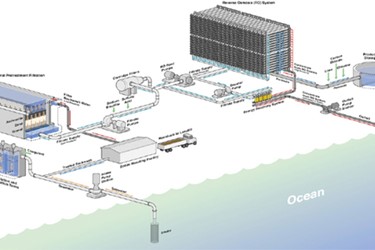
In SWRO plant design, one of the criteria to consider is the intake process of the seawater and the discharge process of the concentrated brine water stream back into the ocean.
Another important criteria to consider in SWRO plant design is engineering the pretreatment process based on the water quality of the specific location. Below, we will briefly discuss why these processes mentioned above are so important and a few ways to handle them.
Intake
The biggest concern for intakes is the potential for the impingement and entrainment of marine organisms. What does that mean exactly? Well, the general definitions for each are:
Impinge: to make a physical impact (on); to collide, to crash (upon)
Entrain (in engineering): to entrap one substance by another
In this context, impingement refers to larger organisms that get stuck to the mesh screen around the inlet.
Entrainment, on the other hand, refers to smaller organisms that can pass through the mesh. Together they simply refer to the collective removal of marine organisms by the intake system.
As of yet, there really isn’t any conclusive, numerical proof that impingement and entrainment cause any significant changes to the surrounding ecosystem, as it is difficult to assess.
However, these issues of impingement and entrainment of conventional mesh intake screen systems can cause significant increases in operating costs.
These operating costs are associated with screen-cleaning, increased energy consumption by intake pumps, and associated chemicals cost due to variations in water quality.
There are a few options for dealing with impingement and entrainment:
-
Intake location and design
Intakes can be placed in areas where there is less biological productivity or lower concentrations of marine life. Intakes can also be designed with higher recovery rates, meaning less water would need to be drawn in from the ocean.
Specialized low-velocity intakes allow marine organisms to escape the induced current from the intake pumps, as well as reducing intake of sediment/silts from the ocean floor. This process assists in avoiding entrainment and impingement.
-
Intake type
There are several different types of intakes in SWRO plant design, and these can be divided into two main groups: surface and subsurface.
The most common intake systems are surface intakes, which include deep water intakes, onshore intakes, and offshore intakes. These are open directly to the ocean and, therefore, use a combination of location, barrier, and deterrents to decrease incidents of impingement and entrainment.
Subsurface intakes are below the seafloor, so they do not don’t cause any impingement or entrainment and have the added benefit of natural filtration through sand. Such systems include four types of well intakes and two types of galleries.
You can find descriptions of these intakes in section 2.2.1 of this paper.
-
Barriers and deterrents
Sometimes it is as simple as putting up a wall or some barrier that fish will avoid to keep them away from the intake. Barriers are things like nets or traveling or passive screens that physically prevent the organisms from getting too near to the intake. Deterrents discourage marine organisms from getting closer by appealing to their avoidance response with things like air bubbles, strobe lights, sound generators, and velocity caps.
You can read about the differences of these preventative measures here.
Discharge/Outfall
Discharging the brine concentrate is the purpose of the outfall system and an integral part of SWRO design. As with the intake, the main concern for the outfall discharge is the potential harm to marine organisms from the elevated salinity of the brine discharge. Concentrated brine water is denser than average ocean water; therefore, upon discharge, the brine sinks to the seafloor. This can increase the localized sea salinity and have negative effects on organisms that are sensitive to changes in the surrounding water composition.
Some options for improving outfall systems include:
-
Diffusers
Instead of pumping out all of the brine concentrate from a single pipe, diffusers can be laid out in series along a pipe to encourage mixing and prevent the brine from settling on the seafloor. There are also specialized low-velocity diffusers that enable enhanced diffusion and dilution of brine over a wider area range.
-
Dilution
The brine discharge is dangerous because of its concentration, but diluting it with more water will lower it. The diluting water can be taken from treated wastewater from treatment plants, power plant cooling towers, or other industrial sources if co-located near these facilities.
-
Galleries and infiltration trenches
These systems are large networks of pipes buried under a thin layer of sand. Diffusing the brine in such a manner reintroduces the brine slowly and over an extended area so that mixing can potentially occur naturally.
-
Zero liquid discharge (ZLD)
These systems have been growing increasingly popular in many industrial SWRO plant design applications. However, they can be costly to operate. In the case of using a ZLD system to recycle seawater desalination discharge, a thermal evaporation process would be required due to the level of salinity in the discharge water. A follow-up crystallization process would be required for the extraction and drying of salt from this brine to be sold accordingly.
More detailed descriptions of these alternate outfall systems can be found in section 3.2 of this paper.
