
Combining CFD And Physical Modeling To Evaluate Water Treatment Plant Performance
By Stuart Cain
Hydraulic modeling has no doubt benefited greatly from computational fluid dynamics (CFD), but physical modeling retains importance and even outperforms CFD in certain aspects. So which method should be relied upon? The answer is both.
Physical Models: The Gold Standard
For years, physical hydraulic modeling of water treatment flow system components was the gold standard for assuring expected performance after installation. The design process for flow splitters, contact tanks, settling tanks, reactors, etc. all benefited from performing scale modeling to study flow distribution, velocity distribution, sediment behavior, and mixing dynamics. These models are not only scientifically useful, but provide a strikingly visual tool that allows engineers to assess their design. Oftentimes, the flow field can be rapidly altered by the insertion of baffles and head loss devices to the model to see, in real time, their impact on the system performance.
The science behind physical hydraulic modeling requires engineering judgment to be used in the modeling process. Consequently, there are inherent advantages and disadvantages associated with this approach. Advantages include:
- generally accurate reproduction of model-to-prototype performance;
- geometric and operational modifications to the model can be quickly implemented and evaluated; and
- the physical model can be very useful in guiding the civil construction process by providing a tactile representation of the final product.
On the flip side, not all physical processes can be scaled simultaneously in a physical model, and they generally require large spaces and skilled craftsmen to construct accurately. Further, laboratory size limitations can be the deciding factor in how large a model can be built; upstream and downstream boundaries are limited by available space.
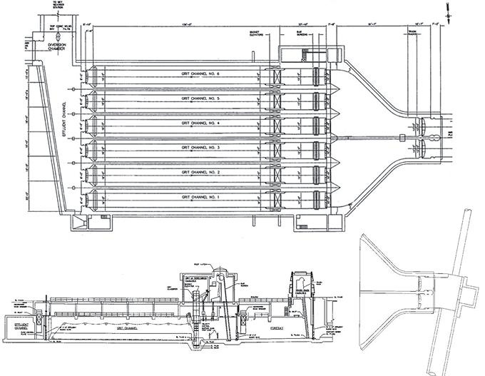
Headworks plan and elevation
CFD: The New Kid On The Block (Relatively Speaking)
Recent and continuing advances in numeric modeling — notably three-dimensional CFD — have reduced the need for physical modeling in certain circumstances. In civil engineering, however, there still remain several classes of complex flow problems that cannot be accurately simulated using CFD alone. In particular, the water treatment industry relies on physical models to simulate the behavior of grit in some complex flow processes, model the operation of pump intake structures, simulate the fate of floatables, and study the complexities of some intricate mixing processes — areas that pose challenges for CFD models. Continuing advancements are enabling large eddy simulations (LES) and direct numerical simulation (DNS) to be more applicable to real-world problems, enhancing the ability of these numeric models to inform the design process.
More often than not, engineers are discovering that a combination of physical modeling and CFD can be very beneficial during the design process and provide needed assurance that the prototype treatment system components operate as intended over the desired range of operating conditions.
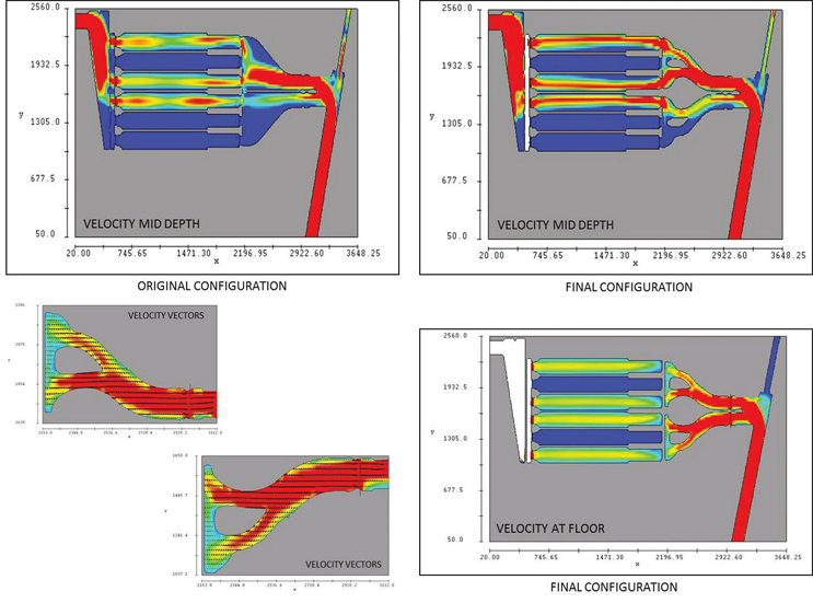
CFD simulation results
Better Together...
Over the past several decades, a symbiotic relationship has developed between numeric and physical modeling in the water treatment industry, and it continues to evolve. Specifically, the two approaches are more often used in tandem to model complex flow processes. The combined approach provides designers and stakeholders the most complete picture of the flow problem of interest by drawing on the strengths of each modeling technique. Further, it is not uncommon for numeric modeling to be used to help set the boundary conditions for the physical modeling domain and reduce the overall footprint (and ultimately, the cost) of the physical model.
As an example, consider the design and evaluation of a water treatment plant pumping station headworks using a combination of both a CFD model and a physical model. The subject station had a nominal flow of 330 MGD, which was desired to be increased to 628 MGD following a plant upgrade.
The existing headworks structure consisted of two interceptor sewer lines (North and South) which fed two 14-foot-wide inflow channels. The inflow channels conveyed sewage into the North and South forebays, each of which expanded from 14 feet to 49 feet wide. Flow from the forebays then passed through three or four of the six parallel grit-collection channels, depending upon total flow volume. The grit channels were operated at various combinations, depending on plant maintenance. Flow from the grit channels was discharged into the effluent channel and the diversion chamber, and finally pumped out through either the influent pump station, wet weather pump station, or some combination of both.
The objective of the study was to: 1) evaluate the flow patterns in the present configuration of the forebay area that may contribute to grit deposition; 2) examine the flow distribution among the operating grit channels for the existing design, and to identify flow patterns that may contribute to any unequal flow distribution among the grit channels; and 3) derive and evaluate design modifications that would significantly reduce grit deposition and improve flow distribution among the channels.
Initially, CFD was used to provide a comparative evaluation of flow patterns and resulting likely grit deposition patterns in the forebays for the existing and two modified forebay designs. The best design was one that reduced the size of the forebays and eliminated areas of low velocity and recirculation. To achieve these goals, “islands” were placed within the existing forebays (to reduce the size of the forebays) and located in such a way as to eliminate areas of low velocity. The final concept, as identified by CFD modeling, is referred to as the “Modified Alternative B Design” and was recommended for further testing with a scaled physical model.
A physical hydraulic model of the existing headworks facility was built to a geometric scale of 1:9. The physical model simulated the entire headworks structure from inlet interceptors to the diversion chamber. Flow distribution data collected on the model indicated that the flow distribution among operating grit channels was more even than originally anticipated and considered acceptable. The uneven grit loading between the North and South forebays was dictated by the skewed flow patterns at the entrance to the forebays. Also, the forebays in the existing facility configuration were too wide, resulting in low velocities and significant flow separations and recirculating flows, allowing the grit to deposit within the forebay region. Modifications to reduce grit deposition within the forebay region were developed and testing was conducted to confirm the performance.
Through a combined CFD/physical modeling approach, a modified design was developed and tested. The modifications included: 1) islands to fill in portions of forebay to form narrow channels to increase velocities; 2) changes to the control structures at the end of grit channels; and 3) introduction of underflow/ overflow baffles in the forebay channels. With these modifications, significant reductions in grit deposition were obtained. Further flushing of grit deposited between the upstream grit channel gates and the bar screens is possible by closing the gates halfway through.

Physical model overview and potential modifications
The Future …
As computational technology advances, numeric modeling will continue to play a greater role in supporting the design process. However, as long as there are physical processes that cannot be accurately modeled using numeric techniques, physical modeling will have its place at the table. Knowing when to use either modeling technique individually, or when to combine the tools, is critical in both accurate prediction of prototype performance as well as meeting project schedule and minimizing modeling costs.
In general, it is advantageous to consult experts in the field of modeling who have knowledge of both CFD and physical modeling prior to deciding which technique, or combination of techniques, to use in evaluating the performance of the components included in the design process. A well-devised hybrid modeling approach to evaluating a water treatment system’s component hydraulics can reliably inform the design process, ensure prototype performance, and minimize schedule delays and project costs.
About The Author
 Stuart Cain, PhD, is the president of Alden Research Laboratory. He joined the company in 1996 to establish the Numeric Modeling Group and has over 25 years of experience in CFD modeling of complex water flow processes, including chemically reacting flows and particulate transport. As part of his technical responsibilities at Alden, he oversees projects involving both physical and CFD modeling of hydraulic processes in water treatment, distribution, and storage systems.