
A Comprehensive Guide To Phosphate Feed System Design For Drinking Water Applications
By Keval Satra, Rajeev Kamalampet, Varenya Mehta, and Mahith Nadella

Phosphate dosing systems are critical for corrosion control, and increasingly important under the mandate of Lead and Copper Rule Improvements.
Phosphate-based chemical treatment is a proven strategy in drinking water systems for both corrosion control and sequestration of metals such as iron and manganese. The addition of phosphate plays a key role in helping water systems comply with drinking water regulatory standards. The U.S. EPA has emphasized corrosion control as a critical measure to reduce lead and copper release into drinking water under the Lead and Copper Rule Improvements (LCRI), which were issued in October 2024.
There are two main types of phosphates used in water treatment:
- Orthophosphates: Contain one unit of PO4, acting as a corrosion inhibitor by forming a protective microscopic film or stable metal-phosphate coating (anodic film) on pipe surfaces, thereby preventing the release of lead and copper into drinking water.
- Polyphosphates: Contain multiple PO4 units chained together and act as sequestering agents, binding with bivalent metal ions such as iron (Fe2+), manganese (Mn2+), and calcium (Ca2+) to prevent scale formation and aesthetic issues caused by iron and manganese.
Blended phosphate (orthophosphate + polyphosphate) offers the combined benefits of corrosion control and sequestration.
Chemical Selection Guidelines
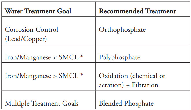
*Note: The SMCL (Secondary Maximum Contaminant Level) established by the U.S. EPA is 0.30 mg/L for iron and 0.05 mg/L for manganese.
Water Quality Considerations
To determine the appropriate phosphate type and dosage, water systems should perform a comprehensive water quality analysis, including the following parameters:
- pH
- Temperature
- Conductivity
- Dissolved inorganic carbon (DIC)
- Total dissolved solids (TDS)
- Calcium and magnesium hardness
- Alkalinity
- Iron and manganese concentrations
In addition, water stability indices such as the Langelier Saturation Index (LSI), Calcium Carbonate Precipitation Potential (CCPP), and Ryznar Stability Index (RSI) should be calculated to assess potential scaling and corrosion tendencies, helping with selection of an appropriate phosphate blend.
Dosage Consideration
- Corrosion Control: The typical target orthophosphate dose is 0.5 - 2.0 mg/L as PO4.
- Sequestering Iron and Manganese: The typical industry practice often involves using a target polyphosphate dose (as PO4) based on a 2:1 ratio for Fe2+ concentration and 5:1 ratio for Mn2+ concentration
Pilot or bench-scale testing is recommended to establish phosphate dosing requirements based on water quality and treatment goals.
Polyphosphates may revert to orthophosphates depending on water temperature and residence times in the distribution system. Therefore, a slightly higher dosage of polyphosphate is often recommended to account for this reversion. A water age of two to three days is generally acceptable, as polyphosphate reversion can accelerate after three to five days of residence time.
Many chemical suppliers provide proprietary blends of orthophosphate and polyphosphate (referred to as blended phosphate), each with varying concentrations and ratios. It is crucial for system designers to consult product-specific information from suppliers to accurately calculate the appropriate dosage rates. Designers should also ensure the feed system is properly sized to deliver the target concentrations of orthophosphate, polyphosphate, or blended phosphate, tailored to the system’s specific treatment goals. Variation in water quality characteristics and flows require adjustments to the phosphate dosage to maintain effectiveness and achieve desired treatment goals. Furthermore, it is recommended to conduct periodic monitoring of phosphate concentrations and related water quality parameters to ensure that treatment objectives are consistently achieved.
Recommended System Components For Phosphate Storage And Feed System
1. Chemical Storage
Chemical storage is typically sized to hold a 30-day supply based on treatment design dosage demand; however, some regulatory agencies may require only a 15-day storage capacity. Chemical storage tanks for phosphate systems are generally made from phosphate-compatible materials such as high-density polyethylene (HDPE), medium-density polyethylene (MDPE), cross-linked polyethylene (XLPE), fiberglass-reinforced plastic (FRP), stainless steel (SS), or glass or epoxy-lined steel. Depending on the chemical usage rate and delivery schedule, phosphate feed systems may include bulk tanks, day tanks, or both. Bulk tanks are typically used when storage requirements range in the thousands of gallons. When large bulk tanks are installed, day tanks are often used downstream to hold a smaller, controlled volume of the chemical, thereby reducing the risk of accidental overfeeding or large spills. As an alternate solution, systems may skip day tanks by providing appropriate controls, instrumentation, and procedures. Intermediate bulk containers (IBCs or totes) may be used when the chemical consumption rate is low, offering a more practical and space-efficient storage solution.
2. Containment
Containment or secondary containment for chemical storage is a safety measure designed to capture and contain chemicals in the event of a primary tank’s failure or leak. Common secondary containment methods include doublewalled storage tanks or an external containment structure. EPA regulations require that secondary containment systems be sized to hold at least 110% of the largest tank within the containment area. However, it is recommended to comply with and adhere to applicable local or state regulations for secondary containment sizing, as these requirements may vary by jurisdiction or application.
3. Building
Phosphate storage and feed systems are recommended to be located indoors in a temperature-controlled environment (i.e., building), as phosphate can become viscous and start freezing at temperatures below 38°F. Buildings provide essential protection from weather conditions such as rain, snow, and extreme heat, helping to maintain chemical stability and prolong equipment life. In addition, housing the feed system indoors simplifies design, installation, and maintenance. These buildings are typically constructed using pre-engineered materials such as fiberglass-reinforced plastic (FRP), precast concrete, concrete masonry unit (CMU) block, or metal building systems. Buildings should include a well-designed truck unloading area to ensure the safe transfer of chemicals from delivery trucks to the feed system’s bulk storage tank. Buildings must include appropriate lighting and HVAC systems that comply with applicable codes for the jurisdiction.
4. Chemical Feed System
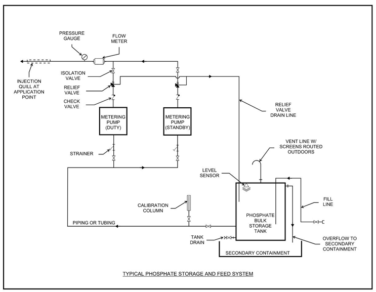
Pre-assembled, skid-mounted feed systems are commonly used in phosphate treatment applications. A typical phosphate feed skid includes a peristaltic or diaphragm metering pump, calibration column, a pulsation dampener, suction and discharge isolation valves, inlet Y-strainers, a discharge pressure relief valve, a check valve, discharge flow meters or sensors, pressure gauges, and a pump control panel. These systems are typically configured with at least one duty pump and one standby or shelf spare pump to ensure full redundancy.
Alternatively, a custom-built feed system can be used in place of a pre-assembled skid system for phosphate treatment applications. When designing a custom system, it is important to include all necessary equipment and instrumentation, shown in the page 12 schematic, to ensure proper functionality and reliability.
5. Chemical Feed Piping
Chemical feed piping or tubing is routed from the metering pumps to the chemical injection point. Whenever feasible, it is recommended to minimize the length of piping by positioning the chemical feed and storage equipment as close to the application point as possible. For piping, Schedule 80 PVC or CPVC is recommended due to its durability and chemical compatibility with phosphate feed systems. For tubing, clear PVC, white polyethylene, or thermoplastic elastomer tubing is commonly utilized for flexible connections and visibility of chemical flow. In outdoor applications exposed to sunlight, it is recommended to use materials with UV inhibitors or to apply a protective coating to enhance the longevity of the piping. Additionally, consider freeze protection measures (insulation or heat tracing) if the location experiences freezing weather conditions.
6. Chemical Injection
Depending on the treatment objective, phosphate may be injected either into basins or directly into pipelines. When added to basins, phosphate is typically dripped from the top of the tank or injected through quills installed in the side walls, with some form of mixing provided to ensure proper dispersion. For pipeline injection, chemical injection quills are used to deliver the phosphate to the center of the flow stream, promoting even distribution. To further enhance mixing, an inline static mixer can be installed downstream of the injection point. Injection quills are generally designed to be retractable for ease of maintenance and are equipped with backflow prevention mechanisms to ensure safe operation. For added redundancy, systems can incorporate dual injection ports at the application point.
7. Controls
Controls for phosphate storage and feed systems include instruments and equipment required to monitor, regulate, and automate the chemical dosing.
a. Instrumentation and Equipment
- Level sensors are installed on storage tanks to monitor chemical levels and activate alarms in the event of low (empty) or high (overflow) conditions.
- Flow meters or flow sensors are used to measure chemical flow to the application points and can be integrated with control systems to automate dosing based on flow rate.
- Pressure gauges or pressure transmitters are placed on the suction and discharge lines of metering pumps to help identify issues such as clogs, leaks, or pump failures.
- Variable frequency drives (VFDs) are utilized to control metering pump speeds, enabling precise, variable-rate chemical dosing based on process requirements.
b. Automation
The operation of the phosphate feed system can be fully automated with a programmable logic controller (PLC) using the feedback signals from the field instrumentation.
8. Ancillary Considerations
a. Power
If continuous operation of the phosphate system is critical, provisions for emergency backup power, such as a generator, should be included in the design. Additionally, an uninterruptible power supply (UPS) is recommended for the PLC and control systems to maintain functionality and prevent data loss during power interruptions.
b. Emergency Eyewash and Safety Shower
An emergency eyewash and safety shower should be installed near areas where phosphate chemicals are stored or handled. The number and exact placement of these safety stations should comply with applicable local, state, and federal safety regulations.
Location Of Phosphate Chemical Injection
The location of chemical injection depends on the treatment goal (corrosion control vs. sequestration), the type of source water (groundwater vs. surface water), and the treatment process at the water treatment plant. Generally, for the sequestration of iron and manganese in ground water application, phosphate should be injected upstream of the oxidation process (e.g., chlorination or aeration). A general rule of thumb is that a separation of 1’ per 1” pipe diameter should be maintained ahead of the chlorine injection point. For corrosion control, phosphate is typically injected into the finished water leaving the treatment plant, upstream of the secondary disinfection residual injection point (chlorine or chloramine).
Typical Process Schematic For Phosphate Feed System
Ancillary Considerations Related To Phosphate Feed Systems
Biological Activity in the Distribution System
Phosphate is one of the limiting nutrients for microbial growth; therefore, excessive dosing can lead to biological growth. This is critical for water systems that maintain a chloramine residual (monochloramine) and utilize phosphate treatment, as there is an increased risk of biological activity within the water distribution system, which can lead to negative water quality issues such as reduced disinfectant residuals and taste and odor problems. To manage this, public water systems can implement periodic free chlorine conversions (also referred to as chlorine burn) for two to three weeks, typically twice a year, to suppress biological growth.
Increased Load to Wastewater Treatment Plants
Phosphates used in drinking water treatment ultimately contribute to increased phosphate loading in the sanitary sewer collection and treatment system. This can place an additional burden on wastewater treatment plants (WWTPs), particularly those required to meet stringent effluent total phosphorus (TP) limits under their environmental discharge permits.
Aesthetic Impacts and Metal Taste
Phosphate treatment does not remove iron or manganese from the water. Instead, it keeps these metals in soluble form, thereby preventing precipitation that would otherwise cause discolored water and staining. However, since iron and manganese remain in solution, their presence may still affect the taste of the water, often imparting a metallic flavor.
Water Quality Monitoring
To monitor and adjust dosage and residuals, water quality parameters such as orthophosphate and total phosphate are periodically measured in both raw and finished water. Orthophosphate is measured directly using the Ascorbic Acid Method (e.g., Standard Method 4500-P E or EPA 365.1), which detects reactive phosphate without digestion. Total phosphate measurement requires an initial digestion step (typically using acid persulfate) to convert all phosphorus forms, including polyphosphates and organics, into orthophosphate, which is then measured using the same colorimetric method. Both results are typically reported in mg/L as PO₄ or as P. Subtracting the orthophosphate concentration from the total phosphate provides an approximate estimate of the polyphosphate concentration for drinking water application.
Cost of Treatment
The cost of treatment is a critical factor in the design and selection of a phosphate feed system to achieve the desired treatment goal. Operational costs include chemical purchases, feed system maintenance, and water quality monitoring. Additionally, systems with complex water chemistry or extensive distribution networks may require higher chemical dosing, resulting in increased annual expenditures. The need for additional treatment at the WWTP to meet TP limits should also be considered. Therefore, utilities are encouraged to evaluate the long-term financial implications during the planning and selection of phosphate treatment strategies.
Conclusions
Designing a phosphate feed system for drinking water involves a careful balance of chemical selection based on treatment goals, water quality characteristics, equipment sizing, optimized design of system components, and regulatory compliance. With the increasing emphasis on corrosion control under the LCRI, phosphate dosing systems are a critical investment in protecting public health. In conclusion, utilities must carefully evaluate their phosphate treatment strategies, considering both immediate and long-term financial and environmental implications.
About The Authors
 Keval Satra, PE, is a project manager and associate at HR Green, Inc., based in the Houston office. He has 10 years of experience in water and wastewater treatment and conveyance projects for municipal clients. Satra holds a master’s degree in Civil Engineering from Texas A&M University and a BS in Civil Engineering from Veermata Jijabai Technological Institute (VJTI), India. He actively contributes to the water industry through his involvement in several volunteering and technical committees with both the Water Environment Association of Texas (WEAT) and the Water Environment Federation (WEF).
 Mahith Nadella, PE, ENV SP, serves as a project engineer at Civitas Engineering Group, Inc., where he is engaged in diverse projects related to municipal water/wastewater treatment, collection, and conveyance. He earned a master’s degree in Civil Engineering from Texas A&M University. Aside from his professional role, Nadella actively participates in various professional organizations, such as AWWA and WEF, contributing to the engineering community. He is currently serving as the vice president for the Southeast Chapter of Texas AWWA Section.
 Varenya Mehta is a water engineer at Civitas Engineering Group, Inc., with over eight years of experience in water and wastewater planning, quality, and modeling. He earned his master’s degree in Civil & Environmental Engineering from the University of Illinois at Urbana-Champaign. Mehta currently serves as the Chair of the Texas AWWA Water Quality & Technology Division and has been actively involved with the Southeast Texas AWWA (SETAWWA) Chapter. In 2024, he served as President of the American Society of Indian Engineers & Architects (ASIE) and is a recipient of multiple honors, including Young Engineer of the Year (ASIE and SETAWWA) and the Texas AWWA Maverick Award.
 Rajeev Kamalampet, PE, is a licensed Environmental Engineer in Texas, with seven years of experience at CDM Smith specializing in water treatment facilities design, construction, startup, and commissioning. He earned his master’s degree in Civil & Environmental Engineering from Texas A&M University, College Station.