
Selecting A Flow Measurement Technology
By Philip S. Stacy
What’s the right flow measurement method for your operation? A leading independent lab breaks down the options and considerations.
What is your flow rate? Seems like a simple question; however, the answer may be quite complex. A lot of variables contribute to whether or not measuring flow is easy or nearly impossible. Variables consist of, but are not limited to, flow conveyance material and size, fluid type, fluid “cleanliness,” acceptable level of uncertainty, and expected range of flow rates and velocities.
Assessing these variables is critical before selecting and installing a measurement technology. To assist with initial selection and evaluation, the following information provides the reader with an overall list, and preliminary evaluation, of flow measurement technologies.
Flow Measurement Technologies
The following is a comprehensive list of available technologies that can be used to monitor flows, regardless of system operation or components, along with brief descriptions of each technology group. This list provides the basis of a technology evaluation, with technologies organized into five different groups by their modes of operation: velocity meters, differential pressure technologies, other closed-conduit devices, open-channel control structures, and generated system curves.
- Velocity meters
- Turbine meters
- Propeller meters
- Vortex meters
- Magnetic flow meters
- Ultrasonic flow meters
- Calorimetric meters
- Differential pressure technologies
- Elbow meters
- Orifice plates
- Flow nozzles
- Venturi meters
- Flow tubes
- Target meters
- Pitot Tubes
- Other closed-conduit flow meters
- Mass flow meters
- Positive displacement meters
- Open-channel control structures
- Weirs
- Control flumes
- Generated system curves
- Dye dilution
- Current meter flow measurement
Velocity meters are flow meters that measure the velocity of a flow which, when multiplied by a known flow area and velocity profile, can be correlated to a volumetric flow rate. For these meters to provide accurate results, they must be placed in locations with uniform flow. Velocity meters can be intrusive or nonintrusive. Intrusive meters may increase the pressure loss in a pipe and are also prone to fouling as they are located within the flow. Nonintrusive velocity meters are typically mounted to the outside of a pipe, but in some cases they may require the installation of sensors and conduits along the pipe walls within the pipe.
Differential pressure flow meters are the most common devices for flow measurement used today. They operate on the basic principle that an increase in the velocity of flow is accompanied by a decrease in the pressure of the fluid under consideration. The pressure drop across the meter is proportional to the square of the flow rate. The flow rate across these meters is obtained by measuring the pressure differential, extracting the square root, and multiplying this by an area and a meter coefficient. The simplest form of a differential pressure-type meter consists of a pressure-detecting element located in the flow path, operating in conjunction with a measuring unit.
Other closed-conduit flow measuring devices include mass flow meters and positive displacement (PD) meters. Mass flow meters, also known as inertial flow or coriolis flow meters, are devices that measure flow as a mass per unit time, unlike other flow meters that measure volume per unit time. To determine the volumetric flow rate, the mass flow rate is divided by the fluid density. If the density of the fluid changes over time or if there are entrained air bubbles, converting the mass flow rate to a volumetric flow rate may not provide accurate results.
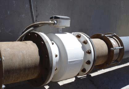
Installed magnetic flow meter
PDs operate by isolating and counting known volumes of a fluid while feeding it through the meter. By counting the number of volumes that pass through the meter, a flow measurement can be obtained. There are many different PD designs, each using a different means of isolating and counting these volumes. These meters are highly accurate on the order of 0.5 percent over a 10:1 range of flow and do not require straight runs of pipe like other flow meters. As these meters collect the flow medium and move it, they are only used for small-diameter pipes, (e.g., 12 inches or less). PD devices have tight tolerances, which can lead to fouling if used in flows that contain suspended particles (100 microns or fewer). These particles can also lead to erosion of the finely machined parts, impacting accuracy. These meters can be constructed out of many materials including plastics and metals.
Open-channel control structures can be used to determine flow rates by measuring the area of the flow stream and the head of fluid producing the flow. Weirs provide a simple means of measuring flow in open channels. A weir consists of a vertical plate or other obstruction placed across the open channel with a level or specially shaped opening or notch. This obstruction increases the water level behind the weir. When a fluid flows over the weir, its flow rate is a function of the water depth above the weir crest. Common weir constructions are the rectangular, v-notch, and broad-crested.
Flume control structures are shaped, open-channel flow sections that force flow to accelerate. This acceleration is produced by reducing the cross-section of the flume. As the flow accelerates, it passes through the critical depth, which results in a unique water surface profile for a given discharge. This allows the use of a head versus discharge relationship for flow measurement. Flumes range in size from small (1 inch wide) to large structures (over 50 feet wide) and can accommodate a wide discharge range (50:1). The accuracy of control flumes is similar to that of weirs. The head loss in a flume control section is about one-fourth of that needed for a sharp-crested weir. In some long-throated flumes, the difference in head loss may be as low as one-tenth of what would be expected with a sharpcrested weir. However, control flumes are generally more expensive than weirs.
Generated system curves can be created by correlating pump speed (if applicable) and system pressure to a known flow rate. The successful use of system curves relies upon obtaining enough pump speed and pressure versus flow data points and verifying the data points over time. This technique would only require the permanent installation of pressure taps and would only impact operations during the flow measurement and verification periods. By accurately measuring the flow, it is possible to determine flow rates under a wide range of flows and/or pump speeds. At locations with varying water levels (i.e., tidal water sources), measurements will need to be taken over a range of water heights to account for changes to the intake and discharge heads. To create a secondary check of pump speed versus flow, pressure differential monitoring devices in the system should be recorded during testing to determine pump speed and flow versus head differential. Generated system curves can be created using any of the flow metering methods detailed above; however, there are two commonly used methods that do not require permanent installation of equipment. The two most common methods for measuring water flow in the field are the dye dilution technique and the area-velocity method using current meters. Providing details of these field techniques would require the writing of an additional article and are not detailed herein.
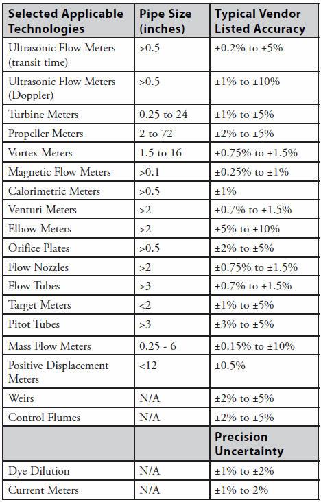
See the following table for information on applicable pipe sizes for each technology and typical vendor-listed accuracies.
Evaluation Criteria
The criteria listed below should be used to evaluate the relative advantages and disadvantages of each flow monitoring alternative and to select and develop those options that are feasible for implementation. The criteria represent key aspects to any ultimately successful flow monitoring program and do not appear in order of priority.
- Options should be designed to operate over the expected range of flow rates.
- Options should provide an acceptable level of accuracy.
- Options should function under expected debris conditions.
- If applicable, options should allow continuous flow monitoring
- If applicable, options should not impact the operation of the condenser cooling system.
- Options should have minimal impact, to the extent possible, on the existing civil/structural features.
- Options must be commercially proven at power-generating facilities.
- If applicable, options must meet all safety requirements.
- If applicable, options must minimize hindrance to facility operations during the installation of the metering devices.
- The technology is available and does not require further engineering development.
Notes:
- When assessing proven industry options at facilities with dissimilar physical, hydraulic, and environmental conditions than the site under consideration, best professional judgment must be used to determine applicability.
- Available technologies are defined as alternatives that provide data in sufficient detail to develop a conceptual design and/ or technologies that have been constructed at other similar facilities.
- Each technology must be qualitatively assessed to identify whether it has engineering advantages over the other technologies. For example, one technology would have an advantage over another if it requires fewer civil/structural modifications for its installation or if it is similar to another option but more accurate.
Summary
Selecting a flow meter system for industrial applications can be challenging given the myriad choices available. This is compounded when the user understands the many significant application variables that influence the choice. This may explain why, historically, industries have struggled to quantify fluid flows, especially large conduit and large flows. Where facilities rely on accurate flow measurement, an operational understanding of the principles behind each flow metering technology is crucial.
References
ANSI/ASME MFC-9M, Measurement of Liquid Flow in Closed Conduits – Weighing Method, ANSI, New York, 1988.
Cheremisinoff, Nicholas P., Applied Fluid Flow Measurement, Marcel Dekker, Inc., New York, 1979.
Miller, Richard W., Flow Measurement Engineering Handbook, McGraw- Hill Publishing Company, New York, 1996.
About The Author
 Philip S. Stacy, director of calibration services at Alden Research Laboratory, is responsible for all flow meter testing performed at Alden’s flow measurement facilities, providing technical and administrative supervision of its Flow Measurement Department to ensure the highest standard for calibrating fluid meters to an accredited certified uncertainty of 0.1 percent in accordance with ISO/IEC 17025:2005.