
Industrial Water Treatment For Inorganic Contaminants: Physical Treatment Processes

By Mark Reinsel, Apex Engineering
This article is the third in a series on industrial water treatment focusing on inorganic contaminants. While regulatory limits are being established (see Part 1), the process of identifying a cost-effective treatment process should be undertaken (Part 2). Potential water treatment processes for inorganic contaminants can be grouped into three categories: physical, chemical, and biological. The goal of this article is to describe the physical treatment technologies that may be considered.
Typical contaminants of concern in industrial waters include suspended metals, dissolved metals, nitrate, sulfate, and cyanide. Common metals and metalloids include arsenic, antimony, selenium, lead, copper, cadmium, and zinc.
Physical treatment technologies can be further divided into three categories:
- Clarification
- Filtration
- Membrane processes
Clarification
Clarification utilizes multiple processes to remove suspended particles, i.e., contaminants that are present in particulate form rather than dissolved. These processes include coagulation, flocculation, and settling. Except for the most rigorous membrane process (reverse osmosis), physical processes will generally not remove dissolved contaminants.
Coagulation is the process of adding a chemical coagulant to destabilize a stabilized charged particle, thereby allowing it to agglomerate with other particles. Common coagulants are ferric chloride or ferric sulfate, aluminum sulfate (alum), and proprietary chemicals provided by companies such as BASF and Nalco. Typical dosages are 10 to 100 ppm. Vigorous mixing is typically used during coagulation.
Flocculation is the process, typically following coagulation or often used as a stand-alone technology, that promotes agglomeration and enhances particle settling. During flocculation, gentle mixing accelerates the rate of particle collision, and destabilized particles are aggregated to create larger precipitates. Flocculation is affected by several parameters, including mixing speeds, intensity, and time. Flocculants are proprietary organic compounds supplied by companies such as BASF and Nalco, with typical dosages of 1 to 5 ppm. Shown below is a jar test showing the large particulates that can be agglomerated and settling by using a coagulant with gentle mixing.
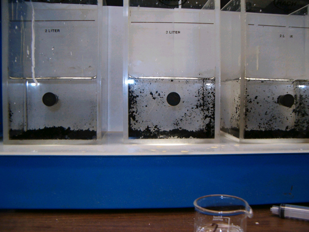
Figure 1. Flocculation in a jar test
Coagulation and flocculation differ from precipitation in that the particles or small particles (colloids) they act upon are not dissolved. Precipitation reactions create particles from dissolved contaminants. Precipitation is a chemical treatment process that will be covered in the next article of this series.
A clarifier is a large piece of equipment that uses coagulation and flocculation, along with settling, to help remove suspended solids. The clarifier also typically uses sludge recycle, whereby a portion of the solids that settle to the bottom of the clarifier (sludge) are pumped back to the clarifier inlet to act as “seed” material for precipitating more solids. The clarifier feed water, flocculant, and recycled sludge are mixed in a “rapid mix tank” at the inlet to the clarifier. Treated water then flows to the clarifier centerwell.
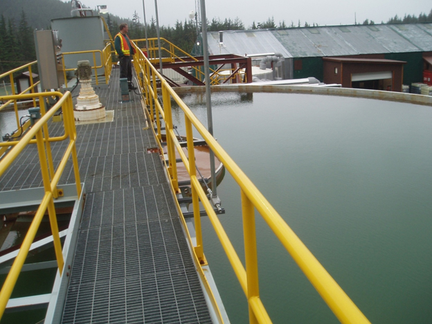
Figure 2. Clarifier at the Kensington Mine near Juneau, AK. The centerwell in the middle of the photo contains turbid water undergoing flocculation.
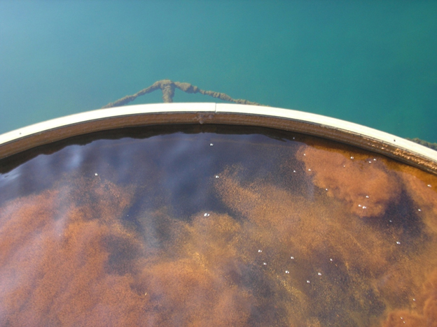
Figure 3. A close-up of the clarifier centerwell at the Central Treatment Plant, located on the Bunker Hill Superfund Site in Kellogg, ID. Metal particulates have agglomerated following pH adjustment and flocculent addition.
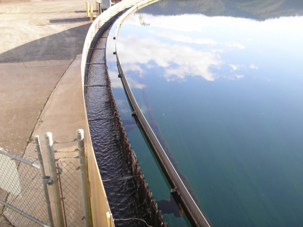
Figure 4. Clarified water (clarifier overflow) exiting the Central Treatment Plant
Sludge that is not recycled (clarifier underflow) is pumped from the bottom of the clarifier for disposal. Sludge may be pumped to a disposal pond (such as at the Central Treatment Plant) but is typically dewatered prior to disposal. Dewatering methods include a lined pond for drying and periodic “mucking”, or some type of filter press (plate-and-frame, belt, etc.). Sludge can then be disposed at a municipal or hazardous waste landfill, depending upon its characteristics.
Filtration
Filtration methods include bag filters, cartridge filters, sand filters, and multimedia filters. Multimedia filters (Figures 5 and 6), which typically utilize anthracite coal, sand, and garnet, are probably the most common filters now in use. These filters are pressure vessels that use downflow operation to remove suspended contaminants and a periodic upflow backwash to transfer these contaminants to a waste stream. Backwashing can be triggered via an adjustable differential pressure switch, a timer (e.g., every 12 hours), or manually (the operator pushes a “backwash” button).
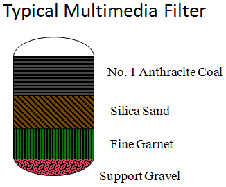
Figure 5. Multimedia filter schematic
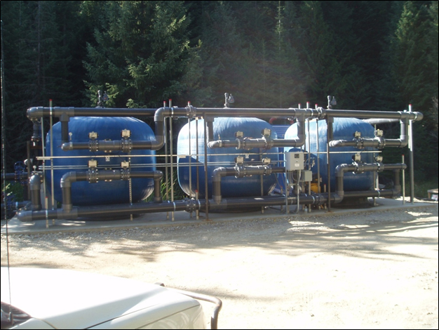
Figure 6. Multimedia filters at the Lucky Friday Mine in Mullan, ID. Filters are typically housed in a building but can also be located outdoors, even in a cold climate such as Idaho’s.
If an upstream clarifier is part of the treatment process, filter backwash is sent to the clarifier. If not, backwash can be settled in a tank or a small sludge thickener.
Membranes
The most common membrane technologies are microfiltration, ultrafiltration, nanofiltration, and reverse osmosis. These have been listed in order of decreasing pore size, increasing removal efficiency, and increasing pressure requirements.
Microfiltration (MF) is the most common membrane process. It provides “sterile filtration” by utilizing pore sizes of 0.05 to 3 microns. MF removes most suspended solids but no dissolved contaminants.
Ultrafiltration (UF) is a “tighter” membrane technology than MF in that it removes colloidal particles, polymers, and bio-molecules. UF (Figure 7) utilizes pore sizes of 0.03 to 0.1 micron and operates at pressures of 30 to 150 psi. UF also does not remove dissolved contaminants.
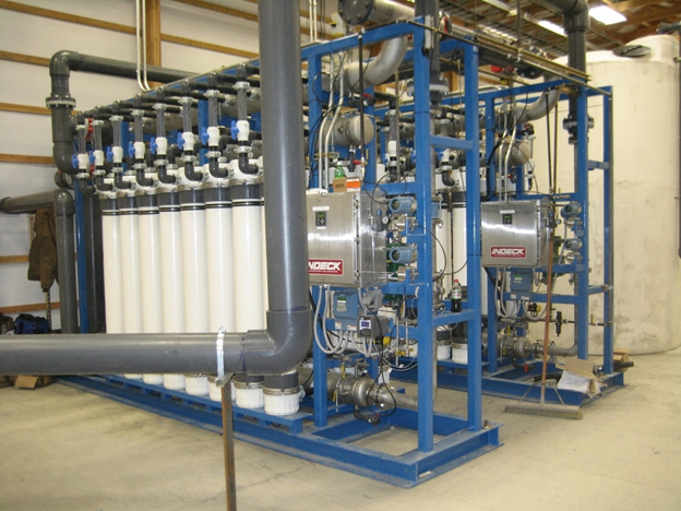
Figure 7. A 500-gpm nanofiltration system at the Montanore Mine near Libby, MT
Nanofiltration (NF) membranes have pore sizes of 0.001 to 0.006 microns; NF systems operate at feed pressures up to 200 psi. NF removes solids, bacteria, high-molecular weight contaminants, and divalent or larger ions such as sulfate. Therefore, it removes some dissolved contaminants. However, NF will not remove monovalent ions such as nitrate and sodium.
Reverse osmosis (RO) is the tightest membrane technology, with pore sizes of 0.0001 to 0.001 micron and feed pressures up to 1000 psi. RO removes solids, bacteria, viruses, and dissolved solids, as does NF. RO removes (“rejects”) 95 to 99 percent of inorganic salts and charged organics, with higher-valence ions having higher rejection rates. Monovalent ions such as nitrate are only partially rejected.
Reverse osmosis is typically considered as a last resort for industrial applications unless the RO reject can be readily disposed of, such as at a public treatment works. Disadvantages of RO include:
- It produces a high-volume, continuous waste stream (RO reject).
- It can be energy-intensive.
- Removal of monovalent ions such as nitrate may be limited.
- It will not remove dissolved gases such as ammonia.
For more information, contact Mark Reinsel at www.apexengineering.us.