
Implementing Granular Activated Carbon Systems: Important Design And Start-Up Considerations
By Scott A. Grieco

As granular activated carbon (GAC) is increasingly employed to treat PFAS, new practitioners can improve their results by knowing what to expect — thanks to data and experience acquired from prior installations.
The impact of per- and polyfluoroalkyl substances (PFAS) and other emerging contaminants (ECs) to drinking source water has caused many water utilities to implement additional treatment technologies. One of the most widely used treatments being used for removal of certain PFAS is granular activated carbon (GAC). However, many drinking water utilities — especially those using groundwater resources — often only employ disinfection and are therefore unfamiliar with the use of treatment technologies such as GAC.
There are five aspects of implementing a GAC system that are not well understood by those who do not regularly design or operate GAC systems:
- Soaking requirements
- Backwash requirements
- pH adjustment period
- Arsenic content
- Disinfection
Soaking Requirements
When new GAC is added to the system, it is dry, and the external void space and internal pore spaces are filled with air. The GAC material only occupies 20% of the bed volume; the remainder is air. The internal GAC pores are approximately 40% of the GAC bed volume. Soaking allows the water to diffuse into the pores and displace the entrained air. Because GAC surfaces are hydrophobic, it takes a reasonably long time to wet the carbon pores and displace the air. The amount of time required is a function of temperature and carbon mesh size. Higher temperatures allow for faster diffusion; conversely, larger particles have longer pores and require more time for diffusion.
At ambient temperatures (50–60°F or 10–15.6°C), soaking requires 48 to 72 hours. The vessel should be filled in upflow mode at no more than 5 gpm/ft2. During the soaking period, the vessel should be isolated from the treatment process and the water held static within the vessel. An example of wetting as a function of time and carbon particle size is provided in Figure 1.
After water soaking, the carbon bed needs to be backwashed or drained and refilled upflow at no more than 2 gpm/ft2 to displace all the entrapped air (from the carbon pores). Air will not be displaced in the normal downflow operation.
If the carbon is not properly wetted/de-aerated, operational and performance problems can result. These include an increase in pressure drop as the air is displaced from the carbon pores and trapped within the bed, and poor or very little adsorption (migration/diffusion of the contaminants to the adsorption sites inside the carbon particles can only occur if there is water in the pores).
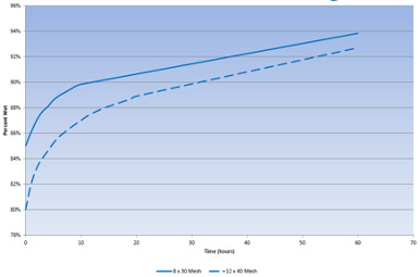
Figure 1. Example wetting curves for 8x30 and 12x40 mesh bituminous GAC. (Source: Calgon Carbon Corporation)
Backwash Requirements
Backwashing of newly installed GAC is required to remove carbon fines and stratify the bed. Stratification allows the larger carbon particles to settle to the bottom of the vessel and provide vertical particle size distribution. Recommended backwash procedures may vary from vendor to vendor, but there are three important aspects that should be followed:
- The specific backwash flow rate required is dependent on water temperature and specific GAC product installed.
- Incorporating a ramp-up period gently separates the carbon and removes entrained air.
- Incorporating a ramp-down period will allow stratification of the GAC.
Table 1 provides general requirements that should be planned into design and operation of the system. Backwash water should be clean and free of solids. Specific requirements will be dependent on carbon product, pH and buffering capacity of the water, and target pH values. The effluent of the backwash needs to be sewer-discharged or collected for discharge/disposal depending on the configuration.
A bed expansion of 25% to 30% should be targeted for backwashing. The following are general guidelines for backwashing:
- Ramp-up period of 5 min. at 0% to 15% expansion
- Backwash period of 20 to 25 min.
- Ramp-down period of 5 min. at 15% to 0% expansion
Reverse flow rates for fluidizing the bed in terms of gpm/ft2 are available for the specific media used at the water temperature of the system. These should be used to quantify the amount of backwash water required. Because water is denser at colder temperatures, it requires less volumetric flow rate to fluidize the bed. It is important to be mindful of the water temperature. If the flow rate utilized is higher than recommended for the given temperature, it is very possible that media can be washed out of the vessel.
It should be emphasized that the primary reason for conducting a backwash on new carbon is to remove fines. As such, the backwash water often contains elevated concentrations (>50 mg/L) of total suspended solids (TSS). It is also typical that the largest concentration will be released within the first 5 minutes of backwashing, with decreasing TSS concentrations as a function of backwash time.
pH Adjustment Period
Often, the start-up of GAC systems exhibits unacceptable increases in the effluent pH, which can result in effluent pH exceeding allowable values. It is not uncommon to observe values greater than 9.5 or 10 Standard Unit (S.U.). The extent of the pH excursion depends upon the water quality (mainly initial pH and buffering capacity).
The pH increase has also been shown to be largely independent of base GAC material and whether or not the carbon has been acid-washed by the manufacturer (Farmer, 1996). The cause of the high pH is due to surface functional groups from the GAC activation process, which drive protonation (attraction of H+) and thus raise water pH values.
Notice that pH decreases as a function of runtime. This is because following protonation, the surface is charge-neutralized with the anions (chloride, sulfate, etc.) present in the water (Farmer, 1996). The pH of the effluent can be elevated for 200 to 500 bed volumes. Additionally, this elevated pH can result in the leaching of aluminum, manganese, and other transition metals from reactivated carbon (Desotec, 2020).
Recirculation can limit the amount of bed volumes required to obtain a neutral pH, but forward-flushing with influent water is the best course of action. Under most scenarios, the required flushing may require two to three days of continuous operation to waste. Thus, planning for sewer connection in the design is always best. However, if a sewer connection is not available, temporary collection for discharge/disposal will be required. The above general table from Farmer et al. provides a general idea of base materials.
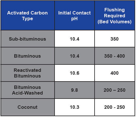
Table 1. Activated carbon type, initial pH, and required rinse volumes for pH stabilization (Adapted from Farmer et. al., 1996)
As can be seen by Table 1, acid-washing may reduce the rinse volume needed to reduce the effluent pH to an acceptable level. However, acid-washing alone is often not sufficient to eliminate initially high effluent pH values. There are also pH-stabilized products available. These can significantly reduce or eliminate the amount of rinse time. The carbon should have an added specification of a maximum “modified contact pH” to show it is a pH-stabilized product.
Results of pH neutralization of a Jacobs-designed system are provided in Figure 2.
As can be seen in these examples, the initial pH of the GAC effluent ranged between 8.8 and 9.2 S.U. Site A (shown in red) is a coconut-based product, whereas Site B (shown in blue) is a bituminous-based product. The source water also appears more buffered at Site A, which required a larger flush volume (~70 bed volumes [BVs]) until the pH started to decrease. This resulted in a total required flush volume of 130 BVs. Site B source water is less buffered and started to decrease within 5 BVs and required about 50 BVs to stabilize the pH at the influent value of 8.1 S.U.
These examples show that the information originally provided by Calgon Carbon in the table may be conservatively high but useful for worst-case planning. The actual volume required will be a function of actual GAC material type, product lot received, and buffering strength of the influent water.
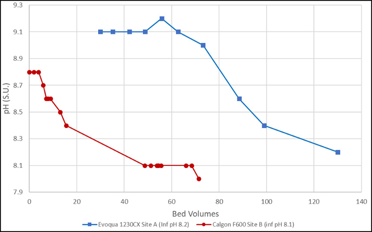
Figure 2. pH vs. bed volumes (data from single-pass rinsing [not recirculated]) (Source: Jacobs)
Arsenic Content
All coal contains some arsenic, which is present primarily within the mineral pyrite interspersed in the coal (USGS, 2005). This means that widely used bituminous and sub-bituminous products often contain arsenic. It is often thought that coconut-based GAC is less likely to contain arsenic. However, as coconut shells used to produce GAC are often harvested from locations with arsenic-rich soil, the coconut tree will take up the arsenic and concentrate it in the coconut shell.
In a study reported in Water Conditioning & Purification, 16 of 20 bituminous and 11 of 19 coconut GACs resulted in detectable levels of arsenic subsequent to leaching tests. As such, when GAC is placed on-line, regardless of the base material source, there is a high likelihood that leachable arsenic present on the activated carbon surface can be transferred to the liquid and end up in the drinking water. Thus, a flush of GAC to drain is often required.
Figure 3 shows the results from a recent start-up using a bituminous-based product.
The various data sets represent different vessels within the overall system. Each vessel received the same bituminous-based product but from various supplier lots. As can be seen, the initial arsenic concentration ranged from 8 to 20 μg/L. For each vessel, the effluent arsenic concentration was reduced to less than 5 μg/L in less than 30 BVs. This supports that arsenic flushing can be accomplished within the same process as required for pH.
Manufacturer-supplied, acid-washed GAC can reduce or eliminate the need for flushing but is more expensive. And since pH flushing is most often required (as discussed above), spending extra money on acid-rinsed carbon for arsenic reduction may not always be warranted.
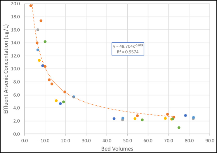
Figure 3. Arsenic concentration vs. bed volume from bituminous GAC startups (Source: Jacobs)
Disinfection
Disinfection of empty adsorption vessels, piping, and other equipment should be achieved through chlorination via standardized AWWA procedures (ANSI/AWWA C653-97).
Although activation of GAC occurs at high temperatures (800– 1000°C) and destroys all the bacteriological contamination on the raw material, it is possible for GAC to become contaminated during transport. Thus, before being put into service, the GAC must be evaluated to verify that it is free of bacteriological contamination. After the GAC is installed, soaked, backwashed, and flushed as described above, the system needs to be checked for presence of bacteria via a rinsing procedure.
Rinsing should be performed at the design flow rate that corresponds to an empty bed contact time (EBCT) of 10 minutes. Two samples for bacterial analysis (coliform and/or heterotrophic plate count [HPC]) shall be collected from the GAC effluent at 10 minutes and 60 minutes of rinsing (or an alternate interval no less than 30 minutes apart). HPC levels less than 500 colony-forming units per milliliter (cfu/ml) are considered acceptable, but state-specific regulations should be considered.
If the system requires disinfection, it can be accomplished by adding a 5% sodium hypochlorite solution to the GAC vessel. However, carbon quickly decomposes the hypochlorite ion, which may compete with bacterial disinfection process. Alternatively, the GAC vessel pH can be elevated to >12 using sodium hydroxide (NaOH). The amount of caustic required is dependent on the water pH, buffering capacity, and vessel size. It is recommended to recirculate the solution for 2 to 3 hours followed by a soak for at least 8 hours. During this process, the pH should be maintained at a value of >12. The solution should be neutralized with hydrochloric acid, circulated, soaked, and discharged to drain.
Summary
As more utilities are considering GAC for PFAS treatment, there are aspects of GAC system start-up that are not widely publicized, and the designer and operator should be aware of these critical items.
Consideration for soaking, backwashing, pH neutralization, arsenic rinsing, and disinfection should be considered as part of a GAC system design. Connection to a sewer for the new GAC system is recommended. However, for systems in remote locations, temporary water collection and transport/disposal at a nearby wastewater treatment plant may be necessary.
References:
Farmer, R. W., Dussert, B. W., & Kovacic, S. L. (1996). Improved granular activated carbon for the stabilization of wastewater pH, Spring Tech. Meet., Am. Chem. Soc., Div. Fuel Chem. 41:456–460.
Desotec, https://www.desotec.com/en/carbonology/carbonology-academy/activatedcarbon-ph-acidity.
Gandy, N.F., and Maas, R.P. (2004). Extractable Arsenic from Activated Carbon Drinking Water Filters, Water Conditioning & Purification. https://archive.wcponline.com/pdf/1104 arsenic.pdf
USGS, U.S. Geological Survey Fact Sheet 2005-3152. (2005). https://pubs.usgs.gov/fs/2005/3152/index.html
Schuliger, W., Nowicki, H.G., Sherman, B., & Nowicki, H. (2010), Granular Activated Carbon Not Working?, www.wqpmag.com, October, 2010.
About The Author
 Dr. Grieco is the global technology leader for emerging contaminants and groundwater treatment within Jacobs Drinking Water & Reuse group. His area of expertise is physical/chemical treatment of emerging contaminants and persistent environmental compounds, with a specific emphasis on adsorption processes and technologies. He has over 29 years of experience in the evaluation, design, and optimization of water/wastewater treatment systems across the public utility, remediation, and industrial sectors. Grieco holds a BS in chemical engineering, MS in environmental engineering, and PhD in bioprocess engineering and is a registered professional engineer in New York.