Developments In Heat Transfer Technology Can Improve Exchanger Efficiency And Reduce Water Demand
By Kevin J. Farrell and Vijay Sathyamurthi, Heat Transfer Research, Inc., College Station, Texas USA
Water’s high heat capacity, high thermal conductivity, and historically low cost make it popular for process heat exchange. Power plants, especially those for liquid cooling applications, withdraw a large fraction of the total demand for water necessary for agriculture, industry, recreation, hygiene, drinking, and wildlife. For example, the condenser water requirement of one 1000 MW nuclear power plant is around 500,000 gallons per minute! Increasing regulations and demand for energy by a continually growing population are now straining our world’s diminishing water supply. According to a U.S. Geological Survey study conducted in 2000, thermoelectric power accounted for 48 percent of the total water withdrawal, of which nearly 70 percent was freshwater. Once-through or open loop cooling accounted for 91 percent of the total water withdrawal for thermoelectric power generation. Future demands for water are expected to exceed availability in all but a few countries.
Heat Transfer Research, Inc. (HTRI) has long recognized that developing cost effective technologies for reducing water use in power plants and meeting the accompanying regulatory challenges is a worldwide need. Our continuing research in cooling water use and air-cooled heat exchangers has provided insights into ways that we can promote sustainability by increasing heat transfer efficiency and reducing water demand. To this end, this article describes two HTRI research programs: the first, on cooling water fouling models; the second, on A-frame air coolers and methods for inclined intube condensation heat transfer and pressure drop.
Cooling Water Fouling
Fouling is a nearly universal problem in the design and operation of heat exchangers. The low thermal conductivity of the fouling layer(s) causes an increased resistance to heat transfer and reduced effectiveness of heat exchangers, as shown in Figure 1. The thermal conductivities of fouling deposit materials can be two to three orders of magnitude less than the underlying metal. Moreover, as deposition occurs, the cross-sectional area is reduced, causing an increase in pressure drop across the apparatus.
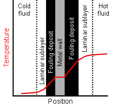
1. Fouling layers add resistance to heat transfer and thus can significantly alter the temperature profile
Cooling water is used in many industries including power generation, refining, and chemical manufacture. A sufficient quantity of water of any quality may be used for cooling purposes, but the fouling tendencies will obviously vary substantially. Cooling systems operate in once-through or recirculation modes. In the former, particulate matter, organisms, and dissolved solids are potential foulants. In recirculating cooling water flows, exposure to atmospheric air introduces additional contaminants. The plant design influences the potential for fouling via the residence time, water consumption, temperatures of the bulk fluid and the wall, and the cooling water velocity.
In the 1990s, HTRI completed a cooling water study that helped quantify the effects that water velocity, wall temperature, and water quality have on asymptotic fouling resistances. The data were used to develop the generalized models in HTRI’s design software, Xchanger Suite. Fouling is obviously highly dependent on the water quality but also sensitive to corrosion inhibitors, which increase fouling, and dispersant additives, which generally decrease fouling. In view of the diminished overall water quality available to process plants and new inhibitors and additives, HTRI has begun a program to revisit and upgrade these water fouling models. Another useful product, HTRI’s R-trend, calculates and trends the fouling resistance for shell-and-tube heat exchangers in single-phase service. HTRI is significantly expanding R-trend’s capabilities in a new product currently in development.
Using field and laboratory data gathered from its fouling test units, HTRI developed a predictive model for cooling water fouling assuming a crystallization mechanism comprised of nucleation and crystal growth. In evaporation and crystallization processes, various salts precipitate in a certain order, depending on operating temperature, pressure, pH, and ionic strength of the solution. Supersaturation, resulting from the difference in the chemical potential in the solution between the heat transfer wall and the bulk of the solution, is the driving force for crystallization and varies with temperature. The solubility of many salts increases with increasing temperature. Scale deposits are formed from salts whose solubility decreases with increasing temperature—an effect known as inverse solubility.
HTRI’s fouling model produces a fouling resistance versus time curve that varies with flow velocity, surface temperature, and water quality, up to an asymptotic value. An empirical correction factor is provided for high concentrations of suspended particles. The HTRI method generally predicts asymptotic tubeside fouling resistances that are lower than the Tubular Exchanger Manufacturers Association (TEMA) fouling factors for untreated cooling water.
The HTRI fouling model was developed for constant heat flux operation when the surface temperature of the fouling deposit remains constant throughout the fouling process. If the temperature of the heating medium stays constant, the surface temperature decreases as the fouling layer thickness increases. The HTRI model is a material balance between deposition and removal.
The tubeside model can be extended to other geometries using an appropriate flow geometry factor. Shellside flow is more difficult to characterize than tubeside flow because bypass and leakage streams divert flow away from the main crossflow stream. Nearly equivalent crossflow and window flow rates in a good shellside design minimize areas of stagnant flow that are prone to fouling. The shellside flow geometry factor is a function of baffle cut, baffle spacing, and tube pitch.
The surface material and roughness are also important influences on fouling. Certain materials are more susceptible to fouling than others. Roughness can affect both deposition and removal, via nucleation and bonding.
As shown in Figure 2, deposits that reduce the available cross-sectional area also increase pressure drop across the exchanger, requiring additional pumping power for the same throughput. Because fouling deposits build up over time, the design fouling resistance typically represents a terminal value. TEMA provides these values for a variety of fluids with different operating conditions. The TEMA listings fail to reflect improvements in design uncertainty or advances in understanding of fouling mechanisms since the origin of the TEMA fouling factors in 1941. The thickness, thermal conductivity, and surface roughness of the deposit strongly affect fouling behavior—positively or negatively. The chemistry of the fouling deposit provides important information about what fouling mechanisms were active during accumulation. Typically multiple layers are present, as shown in Figure 2, which differ in the degree of crystallization, hardness, and difficulty of removal.
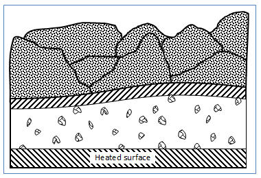
Figure 2. Fouling layer characteristics
While not addressed in HTRI’s crystallization fouling model, biological fouling can result from the accumulation of living matter on heat exchanger surfaces. Biological fouling can be divided into two groups: micro-organisms (including bacteria, algae, and fungi) and macro-organisms (including mussels, barnacles, and seaweed). Once-through cooling systems are prone to this type of fouling because the temperature of the nutrient-rich water is usually near the optimum for biological activity. The presence of biological material on heat exchanger surfaces may promote other fouling mechanisms, like scale formation, particulate fouling, and corrosion. Microorganisms produce sticky substances that may capture particulates. The appearance of the fouled surface varies widely, depending what the organism is and how it is growing. Long filaments of bacteria or algae, slime layers, or extremely rough surfaces from the presence of crustaceans may be present.
Fouling mitigation can be classified as either offline, completely shutting down key processes for cleaning, or online, cleaning the tubes while the equipment is running. Offline techniques clean heat exchangers by mechanical and/or chemical means while the system is not operated, which results in lost production time. They are labor-intensive and expensive, and the waste can be toxic. Moreover, the fouling process starts again immediately after cleaning, and the gradual accumulation of deposits reduces performance until the next scheduled cleaning. These drawbacks make the heat exchanger operation with regular offline cleaning expensive, cumbersome, and inefficient for the entire industrial process.
The online method is an ongoing process which uses mechanical means to keep the heat exchanger clean while it operates. Some cleaning systems also use chemicals which must be carefully adapted to each process, but online mechanical-only cleaning is both environmentally responsible and highly cost effective. Online mechanical cleaning boosts performance in two ways: it does not require system shutdown with temporary loss of operation; and it keeps performance optimal and energy-efficient through continuous cleaning. In addition, online mechanical cleaning eliminates requiring staff time for cleaning services, the purchase of chemicals, and waste disposal.
HTRI is re-evaluating our generalized model for cooling water fouling with the goal to improve it for confident use with currently encountered water qualities and water treatment methods. Future predictive models may shift emphasis to the determination of threshold conditions, the temperature below which—for a given velocity—fouling may be negligible.
A-frame Condensers and Condensation Models for Inclined Tubes
One way to combat the difficulties of cooling water fouling is to eliminate its use altogether. Due to stringent environmental legislation and regulation on the use of natural water sources in many countries, industries are turning to air-cooled heat exchanger technology. Air-cooled condensers are subject to fewer fouling problems and eliminate many of the environmental concerns associated with water-cooled units. The Clean Water Act governs discharges to surface water, with sections 316 (a) and (b) regulating the thermal discharge and intake structures, to minimize adverse impact on aquatic life. While the capital costs associated with air-cooled heat exchangers are higher than comparable water-cooled units for the same heat duty and pressure drop characteristics, they eliminate the need for water and other equipment for water treatment. In some cases, air cooling is the only option available due to local environmental regulations, as in the case of the Astoria Energy Plant in New York City.
Power generation is based on the Rankine cycle, which requires a heat exchanger to condense exhaust steam from the low pressure stage of a steam turbine. The thermal efficiency of the Rankine cycle increases as the exhaust temperature and pressure of the turbine decreases. Consequently, power plant condensers typically operate under pressures ranging between 6 and 58 kPa (abs.), although the Heat Exchange Institute standards specify operating pressures as high as 150 kPa (abs.). Air-cooled condensers in the power generation industry are of the A-frame design and employ both downflow and reflux condensation as shown in Figure 3. The tubes are externally finned to improve the airside heat transfer, while the cross-section is oval, elliptical, flattened, or circular in shape.
The reflux or dephlegmator section of an A-frame condenser relies on gravity to separate the condensing component from non-condensable gases that leak into the system. In the reflux section, any vapor that fails to condense in the downflow section enters from the bottom of the tube, flows upwards against gravity, and condenses on the tube wall. The condensate drains downward due to gravity, whereas the non-condensable gases flow upward due to buoyancy effects and are eventually removed from the system using an ejector. If the inlet vapor flow rate is too high, a hydrodynamic phenomenon known as flooding occurs, which results in cyclic oscillations of the system pressure, droplet entrainment in the non-condensables vent and a general degradation in the performance. To prevent this, reflux condensers operate in the gravity-controlled condensation regime with the inlet vapor velocity below the critical flooding velocity.
The flooding velocity varies with tube geometry, inclination, amount of non-condensable gases, and fluid physical properties. Despite extensive research on flooding spanning several decades, a general flooding model that accounts for all of these parameters has not yet been developed. Existing correlations are often valid only for a few tube geometries, fluids, or operating pressures. Therefore, many of these units may be significantly overdesigned, thus increasing the capital cost.
HTRI is actively engaged in the study of the effect of tube inclination on downflow and reflux condensation in circular and non-circular tube geometries to develop improved design correlations which could reduce excessive design margins and thereby reduce cost. Our research has shown that the critical flooding velocity is nearly ten percent higher for a 60-degree tube inclination with respect to the horizontal as compared to the vertical orientation. Figure 4 compares the condensate film distribution in an inclined tube under stable drainage and flooded conditions.
Our investigation of downflow condensation in a circular tube at two inclinations showed that existing methods for horizontal and vertical intube condensation poorly predict the heat transfer coefficients. These methods should not be applied to design inclined intube condensation in A-frame air-cooled condensers. The two-phase flow patterns differ significantly in horizontal, vertical, and inclined intube condensation.
HTRI is currently investigating inclined intube condensation in elliptical tubes. A few studies in the literature have shown that elliptical tubes increase the flooding velocity, while reducing the airside form drag and lowering the fan power consumption as shown in Figure 5. However, there is no comprehensive investigation of intube condensation inside elliptical tubes. We believe that the elliptical tube cross-section will affect the two-phase flow pattern significantly and thus alter the condensing film heat transfer coefficient compared to inclined circular tubes. HTRI’s investigations in this area will improve design correlations and facilitate energy efficiency.
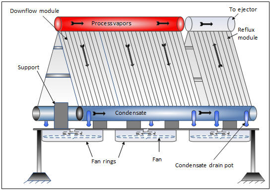
Figure 3. Typical A-frame air-cooled condenser
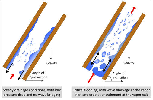
Figure 4. Comparison of steady drainage conditions and critical flooding
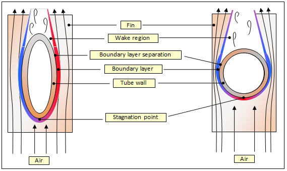
Figure 5. Effect of tube geometry on airflow
Kevin J. Farrell, Director, Computational Simulation & Optical Anemometry, graduated from Pennsylvania State University, State College, Pennsylvania, USA, with his BS, MS, and PhD in Mechanical Engineering. His areas of expertise include fluid dynamics, vibration, and thermal engineering. His responsibilities at HTRI focus on flow-induced vibration, computational fluid dynamics (CFD), visualization studies, and fired heaters.
Vijaykumar Sathyamurthi, Engineer, Research, was awarded his BE in Mechanical Engineering from Nagpur University, Nagpur, India, and then earned his MS and PhD in Mechanical Engineering from Texas A&M University (TAMU), College Station, Texas, USA. At HTRI, he conducts experimental and analytical research, primarily focusing on condensation.
