
Best Practices For Flow Meter Calibration

By Philip S. Stacy, director of calibration services, Alden Research Laboratory
Get to know the basics, best practices, and importance of flow meter calibration from an industry expert.
Flow measurement is integrated into every aspect of modern life, from the measurement of water flow in power plants to the metering of household water. Accurate measurement is vital in both these examples, as well as in other scenarios. Specifically, the power plant must measure correctly for safety, efficiency, and revenue, while the homeowner is interested in being charged correctly. With water supplies being affected by global weather, water measurement is integral to conservation plans. Accurate flow measurement has a positive impact on energy conservation. One of the most expensive problems in environmental control is the handling and treating of potable water distribution.
Flow meters need to be calibrated when a defensible accuracy is required. Sometimes, as in the case of the petroleum industry, meters may be calibrated every day against a built-in calibration device. At the other extreme, some meters may never be taken out of service during the life of the meter — for example, the flow meters found in homes across America. Meters used in the manufacturing and power industries are often subject to periodic calibrations as part of quality assurance programs. In these cases, unless the user maintains a calibration facility, the meter is typically sent to an independent calibration laboratory.
The following discussion reviews the best practices for water flow meter calibration.
Traceability
A calibration is a comparison of the instrument (meter) and a standard. This comparison must be made by measuring the same quantity (e.g., mass versus flow), and the standard used must be accurate. Flow meter calibration is unique; whereas there can be a 1” gauge block for the calibration of a machinist’s micrometer, there is no “gallon per minute” or “cubic meter per hour” test artifact that can be run through a flow meter in order to perform the calibration. Instead, large-scale flows are most often calibrated by the gravimetric method, which uses scales and timers and temperature measurement to determine the flow through the meter under test (MUT). The calibration instruments measuring these parameters must show traceability to higher-level measurements and to national and international standards.
Accuracy Or Uncertainty
Although often used, accuracy is not a term that should be used to quantify calibration results. Accuracy is a qualitative term that should only be used for indicative purposes. Uncertainty is the correct term to express the “accuracy” of a calibration result.
The uncertainty in the result of a measurement generally consists of several components. An uncertainty value is applied to each measurement taken during the calibration process. These are based on instrument calibration data, manufacturers’ data, and laboratory experience. For example, in the case of volumetric flow measurement using the gravimetric method, the uncertainty of the lab flow is directly related to the measurement of these primary parameters and the instrumentation used for their measure; all must be traceable to a recognized international standard and must have an associated uncertainty budget, or allowance. The individual measurement uncertainties are combined to provide a confidence level in the flow measurement result.
In addition, the user should evaluate the final “as-installed” uncertainty of the meter, which may include differences in the piping between the calibration piping and installed piping as well as the ancillary instrumentation, which likely carries with it a different uncertainty value than the equipment used in the laboratory. In the case of clampon style ultrasonic meters, for example, the calibration is almost always performed by attaching the meter’s transducers to laboratory pipe. As such, the end user should budget some additional uncertainty when the transducers are later installed on plant piping.
Accreditation
Laboratory accreditation provides the consumer seeking meter calibration with reassurance that the laboratory has been independently evaluated and has demonstrated competence in the field. At the time of this publication, the ISO/IEC 17025 is a quality, internationally recognized standard for calibration laboratories, to which accreditation demonstrates technical competence for a defined scope of work and adherence to a laboratory management system.
Fluid Properties
Understanding the fluid properties of water at both the operating and calibrating conditions is critical to providing useful calibration data. The interaction between the flow meter and the water is affected by the water temperature, density, operating pressure, Reynolds number, and conductivity. Reynolds number is a nondimensional value based upon the viscosity and velocity of the fluid through the meter. For differential-producing meters such as flow nozzles, Venturi meters, and orifice plates, it is desirable to calibrate at the operating Reynolds number of the meter. In general, meter calibration should be conducted using a fluid having properties as close to the actual operating conditions as possible to reduce errors associated with using the incorrect fluid properties. Often it is impossible to achieve the operating conditions in the laboratory, and extrapolation of the lab data is required. Extrapolation of calibration data is a subject worthy of its own paper, but an incorrect application of fluid properties during the calibration process can result in a significant error when using the meter in its final installation.
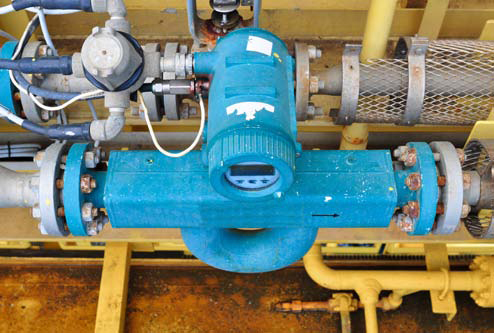
Coriolis flow meter
Simulated Installation Conditions
The velocity distribution of the flow as it enters a meter can affect a meter’s response. The goal of any meter installation is to provide the best possible piping conditions upstream and downstream of the meter; the American Society of Mechanical Engineers (ASME) and International Codes provides guidance for meter installations. Ideally, the flow entering a meter should have a fully developed velocity profile. This is dependent on the internal pipe diameter, pipe roughness, Reynolds number, and length of pipe; it is achieved by providing many diameters of upstream pipe free from disturbances such as elbows, valves, and diameter changes. It should be noted that, although some types of meters are less affected by the adjacent piping, it is generally recommended to provide long, straight lengths of pipe upstream and downstream of the meter. If the site installation is not compliant to that guideline, it is recommended that the piping during calibration be arranged to simulate the site installation configuration as closely as possible. ASME codes provide allowances (added uncertainty), which may be added to a meter calibrated in the (ideal) laboratory setting. Interestingly, the additional installation uncertainty can be large enough to overshadow the calibration uncertainty. In cases such as this, it is prudent to reproduce the plant conditions during the laboratory calibration.
Cost Of Calibration
There is a cost to the consumer associated with providing the best possible meter calibration. The cost of calibration is typically a function of the size and number of test points recorded. Differential-producing meters are nonlinear devices in which the signal varies with the square of the flow, and these often require more data points to characterize the meter performance. These meters can have multiple sets of piezometers, or “taps,” which add to the cost (laboratory instrumentation is costly to maintain under typical quality programs).
A base price is often determined as a function of meter diameter and includes a predetermined number of taps and data points. For example, the base price for a 12-flow-point calibration of a 16” diameter meter will be approximately $2,500, with additional tap sets adding about $1,000 each and additional data points adding about $50 each. Most differential-type meters are calibrated with two tap sets to provide redundancy. Electronic flow meters such as magnetic, ultrasonic, and Coriolis are often calibrated by recording six “as-found” and then six “as-left” data points if the meter requires adjustment to bring its performance to the customer’s specification. There may be several iterations of data required to adjust these meters before finalizing the as-left data. A 6” magnetic flow meter would cost approximately $1,300 for a 12-point calibration of this type. Accredited calibrations, to ISO/ IEC 17025 for example, require additional data and analysis, which can more than double the cost of the 6” meter in the example above.
The major costs of calibrating an existing meter are related to its removal, shipping, and reinstallation after calibration. These costs are highly dependent on the meter’s location within the plant, which affects the cost of its removal and reinstallation, and the geographical location of the plant with respect to the calibration facility. A facility with a meter bolted to upstream and downstream piping that is located at the ground level will likely cost less to remove than a welded-in-place meter located on the ninth level over open space. Those costs are estimated to range from $5,000 to $75,000.
Summary
Water is an important resource, and its measurement is crucial in determining the operational efficiency of power plants and no less important in conserving supplies of drinking water. Meters used for water flow should always include a statement of the meter’s measurement uncertainty. When this uncertainty must be determined by calibration, many factors contribute to an accurate flow calibration, and an oversight or error in any of these factors can contribute to significant uncertainty in the results. Meticulous attention to detail (e.g., fluid properties, piping, and appurtenances configuration) and collaboration with a traceable calibration facility are recommended to provide a useful flow meter calibration.
References
ANSI/ASME MFC-2M, Measurement Uncertainty for Fluid Flow in Closed Conduits, ANSI, New York, 1983.
ANSI/ASME MFC-9M, Measurement of Liquid Flow in Closed Conduits — Weighing Method, ANSI, New York, 1988.
Cheremisinoff, Nicholas P., Applied Fluid Flow Measurement, Marcel Dekker, Inc., New York, 1979.
Hayward, Alan T.J., Flowmeters — A Basic Guide and Source-Book for Users, John Wiley & Sons, New York, 1979.
ISO 4185, Measurement of Liquid Flow in Closed Conduits — Weighing Method, ISO, Geneva, 1985.
About The Author
 Philip S. Stacy, director of calibration services at Alden Research Laboratory, is responsible for all flow meter testing performed at the company’s flow measurement facilities. He provides technical and administrative supervision of Alden’s flow measurement department to ensure the highest standard for calibrating fluid meters to an accredited certified uncertainty of 0.1 percent in accordance with ISO/IEC 17025:2005.