
Simple Steps To Drive Down The Cost Of Desal
By Tomer Efrat and Hadar Goshen
Using natural gas to power the mechanical vapor compression unit — the “heart” of conventional desalination and its most energy-intensive process — may prove to be an economic game-changer.
In a time when gas prices are plummeting across the globe, traditional methods employed in many industries must be reexamined from a techno-economic standpoint. One such example is the water desalination industry, and more specifically, the mechanical vapor compression (MVC) application.
Conventionally, an MVC unit utilizes an electric motor to drive its compressor, which is the central component in this desalination method, accounting for 80 to 90 percent of the plant’s overall power consumption. The compressor induces the temperature difference required for the evaporation/condensation process, in which seawater is converted to high-quality distillate.
The electric motor driving the compressor can be replaced with a gas engine, thus dramatically reducing the operation costs.
The gas engine (which is standard industrial equipment) utilizes all types of gas — from petroleum gas to natural gas — in an inner-combustion chamber, to facilitate the mechanical drive to the compressor. The waste heat from the gas engine can be further utilized in the MVC unit to reduce the heat transfer area, which in turn reduces the capital costs of the unit, making the investment all the more worthwhile.
These modifications can be done in new plants or as a retrofit to existing plants. In this article, we review the economic implications and the advantages of the innovative solution of a gas-driven MVC unit.
Natural Gas In The U.S.
Natural gas has served a growing role in the U.S. economy in the last decade, second only to petroleum as the primary source of energy and the primary source of energy when it comes to power generation.1 Since 2009, the U.S. has been considered the world’s largest producer of natural gas, increasing the natural gas availability for local markets. As a result, the U.S. power and industrial markets benefit from some of the lowest natural gas prices in the world. These low prices, together with other benefits of using the natural gas as an energy source, such as its environmental aspects, encouraged a rapid growth in the use of natural gas for a growing number of industries. As a result, the natural gas consumption in the local U.S. market has increased by about 25 percent in the last decade,2 during which period the U.S. natural gas reserves have climbed by 49 percent. These figures alone indicate the large potential that still exists for the growth of natural gas consumption in the U.S., encouraging developers to introduce more innovative ways to utilize natural gas.
MVC Process Description
The MVC process is an evaporation-condensation distillation process utilizing a centrifugal compressor to generate the motive energy for distillation.
The feed water enters heat exchangers where it is heated by the discharged distilled water and brine, thus recovering process heat. Next, the feed water enters an auxiliary deaerator/ condenser in order to remove noncondensable gases (NCG) from it. The heated and deaerated feed water then flows to the evaporator through spray nozzles, forming continuous, thin water films over the horizontal tubes of the evaporator.
Since the suction of the compressor provides a pressure lower than the equilibrium pressure of the brine film on the tubes, part of the brine flashes into vapor. The vapor generated passes through a set of deflectors, louver demister, and mesh demister to remove droplet carryover and maintain the purity of the distillate. The vapor is then compressed by the compressor and discharged into the tubes of the evaporator at a pressure that is now slightly higher than the liquid-vapor equilibrium pressure. The vapor inside the tubes condenses, transferring its latent heat of condensation across the walls of the tubes to the brine flowing on the outside, thus providing the required heat to initially raise the temperature of the brine to its liquid-vapor equilibrium temperature, and then to evaporate part of the brine. The newly created vapor is then drawn out by the compressor. The condensed vapor from the evaporator is collected and pumped out as distillate. The brine and distillate are rejected out of the evaporator by pumps, and on the way out they exchange heat with the incoming feed water and then flow out.
This process can be done in one effect, as well as with two or three subsequent effects.
The MVC low-temperature process is suitable for industrial uses,3 such as boiler feed water, flue gas desulfurization (FGD) make-up water, cooling-tower make-up water, and others.
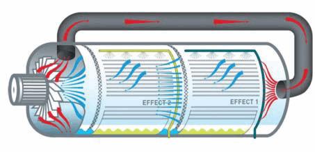
Flow scheme of MVC (mechanical vapor compression) unit
Driving The Compressor With A Natural Gas Engine
As previously mentioned, the main innovative feature of this MVC method is driving the MVC unit with a gas engine. A gas engine, as opposed to an electric motor, is an internal combustion engine where the gas is mixed with air, compressed, and burned to yield mechanical power. This power can be converted to electricity (by coupling it to an electric generator) or used as a mechanical drive (not very different from the mechanism in a natural gas vehicle). In the case of MVC, it is not necessary to convert the power into electricity and then back to a mechanical drive. As a result, the conversion/ transmission-related losses are spared, as well as the equipment costs associated with them.
As the gas engine rotates at relatively low speeds (1,400 to 1,800 rpm) and the compressor usually rotates at higher speeds (2,500 to 3,600 rpm), the gas engine is connected to the compressor via a gearbox, which increases its rotation speed. The dimensions of the gas engine are fairly similar to those of an electric motor, so it can still be installed on top of the unit.
A gas infrastructure is required on-site. The required gas pressure at the inlet to the engine is between 1.5 and 50 pounds per square inch gage (psig), depending on the engine size. A pressure regulator can be an integral part of the system. The gas engine can consume natural gas, biogas, petroleum gas, coal seam gas, and other types of fuel gas.
Heat Recovery
The typical efficiency of a gas engine is about 40 percent, meaning that about 60 percent of the energy input will not be converted to mechanical energy. Instead, it will be lost as heat energy, where 40 percent is lost to the atmosphere (whether through the exhaust gases or by radiation), and the additional 20 percent is lost to the engine cooling systems (jacket water cooling or oil cooling).
Therefore, when considering the use of a gas engine, utilizing its waste heat would be a smart move.
In an MVC/gas-engine integration, there are several options for use of the waste heat:
1. Heating the feed water — As mentioned, the MVC incorporates two heat exchangers that recover the heat from the product and brine streams in order to preheat the feed water. In this innovative solution, the waste heat from the gas engine is utilized for the same purpose and contributes to minimizing the heat exchange areas, thus reducing cost.
The waste heat can be recovered from the gas engine’s oil cooling cycle or the jacket cooling water cycle.
2. Producing steam — The exhaust gases of the gas engine are released at a fairly high temperature of 400 to 500°C (750 to 930°F). This heat source can be utilized to produce steam by employing a heat recovery steam generator (HRSG). The source water for this steam would be the product water of the unit (or service water).
The steam can be used to heat the MVC unit at startup, to assist a stripping process (if the feed water contains any constituents that should be removed prior to entry to the MVC unit), or sent to any other industrial processes, thus improving the heat rate of the plant.
Carbon Dioxide Recovery
An additional benefit from the exhaust gas stems from its chemical composition. The main emission product from natural gas combustion is carbon dioxide (CO2), which can be harnessed to increase its value.
When the designation of the distillate from the MVC unit is drinking water (rather than high-quality process water/boiler feed water), a post-treatment stage is necessary. Usually, the post-treatment process involves the dissolution of limestone (calcium carbonate [CaCO3]) into the product water to regain hardness (calcium), which in turn decreases the corrosion potential of the water (calculated by Langelier saturation index [LSI]). When looking at the carbonate system, this dissolution takes place at low pH levels, which are achieved by dosing either acid or CO2 prior to the limestone reaction chamber.
In the case of using a gas engine, the CO2 can be recovered from its exhaust gases and used in the post-treatment process, thus decreasing greenhouse gas (GHG) emissions, as well as reducing the operational expenses (OPEX) of the plant.
Techno-Economical Evaluation
A techno-economical evaluation was performed to assess the benefits of this system. In the presented case study, we considered an MVC-1000 unit, a fairly commonly used unit from IDE Technologies. This two-effect unit produces 1,000 m3 (264 kgal)/day (or 264,000 gpd) of distillate, with a specific power consumption of about 11 kWh/m3 (of which 9.6 kWh/ m3 accounts for the compressor).
The electricity price was taken as $0.1/kWh and natural gas price as $2.5/MMBtu (1 MMBtu = 1 million BTU [British thermal units]), which is a conservative value. From the investment point of view, the return period is 25 years, with 6 percent interest. Under these assumptions, and without including the heat and CO2 recovery, we have calculated the OPEX and capital expenses (CAPEX), which, when summed up, yield the water cost.

MVC Electric vs. MVC Gas Comparison Chart
The OPEX takes into account electricity, gas, chemicals, labor, and maintenance costs. The CAPEX takes into account the cost of the MVC unit, gas engine, and the balance of plant (BoP).
As can be seen in the comparison table (above), the operational expenses are reduced by more than 55 percent and the total water cost by 35 percent. With an integrated heat recovery, the costs reduction is even higher. The ROI is approximately one year, which makes this a rewarding proposal for both new and refurbished plants.
Enumerating Value
1. Unit efficiency and heat rate improvement
- Waste heat can be recovered from the gas engine to decrease the specific cost of the MVC unit (by minimizing the heat transfer area).
- At the same time, the waste heat can be used for steam production, thus increasing the heat rate of the plant.
- CO2 can be recovered to the post-treatment (remineralization) process, to decrease the OPEX of the plant.
2. Electric infrastructure minimization — No need for medium voltage transformer, switchgear, MCC, cables, and conduits.
3. Easy refurbishment of existing plants — As weight and dimensions are comparable in size, it is easy to replace the electric motor with a gas engine.
As gas prices drop, it becomes evident that integrating a gas engine instead of an electric motor in an MVC unit, in order to drive the centrifugal compressor — the “heart” of the unit — eliminates the need for most of the electricity in the plant.
While not inflicting higher costs, the gas engine variation is able to reduce operation costs by more than 55 percent, and the total water cost by a third, with an ROI of about one year. The use of heat recovery will further increase savings and improve the heat rate of the plant. This modification of installing a gas engine is possible in both new and refurbished plants, making it a promising solution for the desalination market.
References
1. Monthly Energy Review - Energy Information Administration. [Online].; 2016 [cited 2016 April 19. Available from: http://www.eia.gov/totalenergy/data/monthly/.
2. U.S. Natural Gas Total Consumption (Million Cubic Feet). [Online].; 2016 [cited 2016 April 19. Available from: https://www.eia.gov/dnav/ng/hist/n9140us2A.htm.
3. Kronenberg G, Lokiec F. Low-temperature distillation processes in single- and dualpurpose plants. Desalination. 2001 May: p. 189-197.
About The Authors
 Tomer Efrat is the process engineering manager at IDE Technologies, where he is responsible for the process design of IDE Technologies’ seawater desalination and industrial water treatment plants. Tomer has more than a decade of experience in desalination and treatment of seawater and industrial water. He has been with IDE for more than 10 years, first as a process engineer, and later as deputy manager and manager in the thermal process department. In these positions, Tomer has been closely involved in the commercial activities related to the process design of seawater desalination, industrial water treatment, and ice plants. In addition, he leads a team of highly skilled process engineers in the execution and implementation of the company’s R&D program and supports sales and marketing and business development activities. He holds several patents and pending patents for water treatment technologies. Efrat has an MBA and a B.Sc. in mechanical engineering from Tel Aviv University.
 Hadar Goshen is the thermal desalination process team leader at IDE Technologies, and has been overseeing advancements in IDE’s thermal desalination since 2015. He previously served as a process engineer for five years, where he participated in project process design and worked with external suppliers. Goshen holds two patents for the water vapor deposition process and freeze desalination. Goshen has an M.Sc. in systems engineering from the Technion – the Israel Institute of Technology, and a B.Sc. in mechanical engineering from Tel Aviv University.